Welcome to Laser Pointer Forums - discuss green laser pointers, blue laser pointers, and all types of lasers

Buy Site Supporter Role (remove some ads) | LPF Donations

Links below open in new window

FrozenGate by Avery

First laser assembly problems

Ralan

0
Joined
Apr 12, 2015
Messages
20
Points
0
Hello laser forums! I am very new to what I am hoping can turn into a great hobby involving lasers, it is a fascinating technology.

The short version is I am a computer sciences major and I was recently inspired to build a customized laser gun using a 200mW 532nm Green Laser Module from DX. For a casing I am using a toy gun from Walmart that I took the toy parts out of, it has 3 aa batteries (one of which I have a dummy battery in so that I have 3V output) and of course a basic switch to activate the toy.

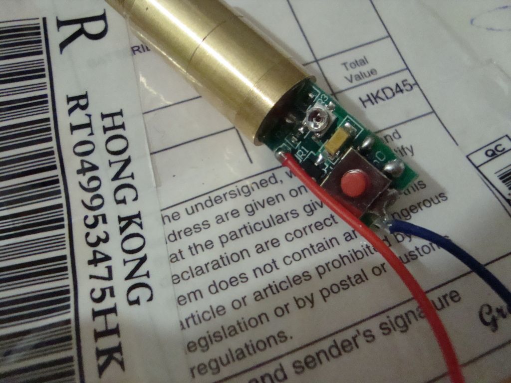
When my laser module arrived, the wires were not attached to the driver, I attempted to solder them using pictures such as this: http://img714.imageshack.us/img714/2371/dsc000102.jpg

I also have the button on the driver glued down and shorted. I was unsure of this part, I hope I didn't mess something up.

But when I have the assembly set up and I click the switch, I get nothing. I can confirm that I am getting power to my solder points, but as I am essentially learning on the fly (despite the reading I did while waiting for the laser) I know I could have very easily made a mistake with the setup.

If any of you more experienced laser techs could help me troubleshoot and get my laser working, I would be insanely grateful.

I am also stoked that I found this forum, as I have seen some interesting posts in my short time browsing the site. Laser technology is something that I am becoming increasingly interested in.
 
Last edited:


You should add your location to your profile before asking more questions, this is a global forum, people need to know at least what country your in.

Post a link to the module you purchased, take photos of what your doing and post those too, then myself or others can see what you did wrong. The module should have had two wires or else just a spring.

If your going to stick around here you should also post in the Welcome forum and tell us about yourself so we can get to know you.

Alan
 
Last edited:
Ive had a few of these modules that ive used and abused! But ive never seen the positive wire soldered there! Looking at the pic you posted it looks like a different driver also. I've yet to order a green module from dx so the pic I posted is a general reference.
good luck and PEW PEW on!!!!

edit: heres a shot of the two driver/module assemblies I have right now. I blew a few and tossed them so only the two.

attachment.php
 

Attachments

  • greendriver.jpg
    greendriver.jpg
    38.1 KB · Views: 270
Last edited:
Was the driver working before you did all
the mods? Sometimes they never work in the
first place. I also notice that you are a
PC tech. Laser diodes are far more ESD
sensitive than a PC. You should be wearing
an ESD strap at all times when handling
these laser modules. If you did not, it is
possible that the diode was damaged by ESD.
 
Yeah sorry for the lack of info, I was pretty tired when I made the original post, let me elaborate a bit.

I was expecting the wires to come attached to the unit, so I really kind of jumped the gun with putting it together, excitement got the best of me.

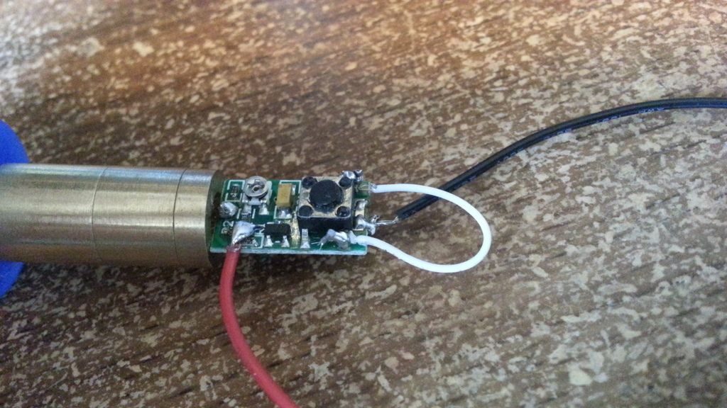
I did not test the module first, I thought it was going to be simple to solder wires, attach to power supply and voila. The picture that I originally went off to solder the wires had the negative wire in the wrong spot I believe. The white wire is my attempt to short the button, I originally thought that maybe it was the cause of the "nothing happening" problem.

Here is the unit that I ordered: 200mW 532nm Green Laser Module (3V 11.9mm) - Free Shipping - DealExtreme

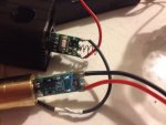
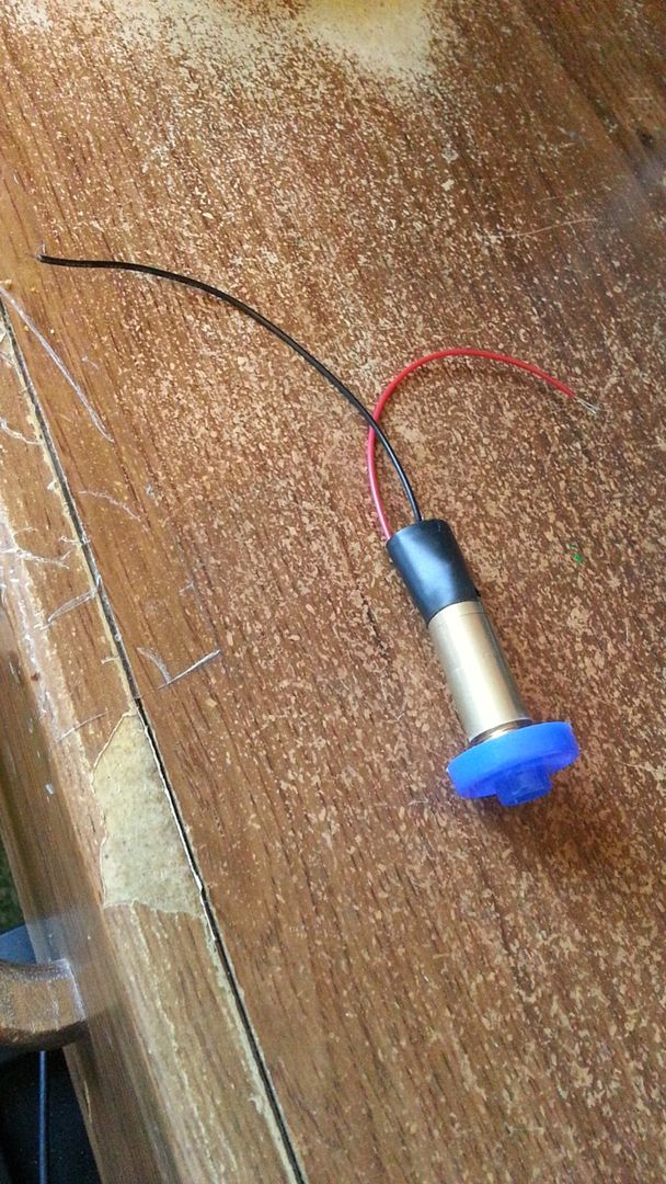
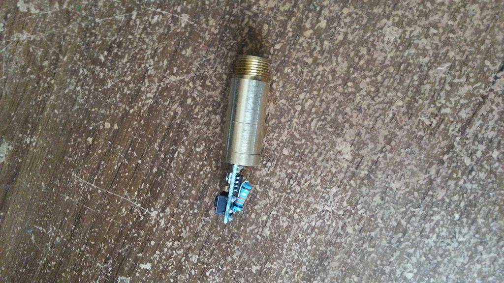
Here are some pictures, I did document my project well.

20150412_152513_zpsdltqxqyk.jpg


20150411_122325_zpsmubyomue.jpg


20150411_112243_zpsnodxun4r.jpg


The blue cap is for a little housing case so that it sits inside the toy gun, there is just a spot of glue holding it on the end.

The picture I used as reference for soldering the wires is here:
328701_zpsttmm41un.jpg


I would love to visit this forum regularly, so I will make sure to post on the Welcome forum as well, thanks!
 
Last edited:
Okay, well maybe all is not lost. This
time, use your ESD strap (you do have one,
right?) and touch the positive wire
directly to the brass module. See if you
get any light. DON'T solder it there, just
connect it there temporarily. Try working
the button and whatnot to see if it
produces any joy. If not, then I'm afraid
it's hosed.

Don't feel bad. I killed my first laser
build, too. Actually, I killed it at least
3 times!
:spank: :twak:
So don't feel bad. I eventually got it
working. In fact, it's working so well now
that I'm planning on doing a writeup on it
soon once everything is all glued down into
da presticion. :)
 
By brass module, you do you mean the outermost casing or the positive prong?

I unfortunately get the feeling that I forked it up pretty good by getting solder-happy and not just testing the wires to it first. I was also really confused as to where exactly the wires went, since I wasn't expecting to have to solder the wires to the driver.

Assuming that this module is no good, where would you recommend I get another? I would really like to make this work, with the end product being a green burning laser.

The DX one took about 21 days to arrive which is a grueling wait. I spent about $30 on the module, is there any US area outlets that I could buy a laser of similar specs and price?

At any rate, I appreciate all of the help and I am still eager to make this work.
 
By brass module, you do you mean the outermost casing or the positive prong?

Yes, the only brass there is on the module.

I unfortunately get the feeling that I forked it up pretty good by getting solder-happy and not just testing the wires to it first. I was also really confused as to where exactly the wires went, since I wasn't expecting to have to solder the wires to the driver.

Assuming that this module is no good, where would you recommend I get another? I would really like to make this work, with the end product being a green burning laser.

They cost a little more, but the modules
sold by techhood on eBay are slightly
better quality. There's a good chance that
this "200mW" module, if it had ever worked
at all, was only 60-100mW.

The DX one took about 21 days to arrive which is a grueling wait. I spent about $30 on the module, is there any US area outlets that I could buy a laser of similar specs and price?

No
If you still can't get it to work, send it
here and I can take a look at it. I don't
charge anything if it is completely
inoperable, only return shipping if you
want the spare parts.
 
Okay thank you, I am a bit busy at the moment with finals right around the corner, but I do have one more question: The module I bought said it was 3V and for power, I had two AA batteries in series, which should be 3-3.1V. This sounds incredibly simple but that should be a proper power source right? I read something that said I needed the required voltage + 1.5 volts but I couldn't verify if that was actually necessary. I will also take a look at the ebay modules, thank you for the reference.

Also, I would like to test my module more just to make sure that I can't get it to work, but with my inexperience and the indirectness of the guides and stuff I found, where should my power wires actually go? I still don't know if they are in the right places. If there is a "wiring laser modules for dummies" that I could be pointed to, I would love to learn how to work with these just by looking at them.
 
Last edited:
If they are good fresh cells, then yes, it
will be enough to power it. If they are
drained, even a little bit, below about
2.8V, then there won't be any output at all
and it will look like it's broken. I don't
think that is the whole problem, since it
looks like the P+ wire is in the wrong
place. Get a 14500 or 16340 cell to run
it, though. It will work much better.
 
I will definitely look into getting better batteries for it. I was actually wondering about the voltage, if I get those cell batteries recommended, do I have to get batteries that offer exactly a 3V output? Would more overload it or would the driver regulate the extra voltage?

Also, if you had any advice as to where my p+ wire should be, it is the one that I just couldnt get a straight answer on. The negative wire seemed to always go on the back end of the driver, right behind the button.

I also want to thank you for all of the advice, I know that schooling a newbie can sometimes be a pain in the rear but I always love being able to talk to someone that knows their stuff.
 
I will definitely look into getting better batteries for it. I was actually wondering about the voltage, if I get those cell batteries recommended, do I have to get batteries that offer exactly a 3V output? Would more overload it or would the driver regulate the extra voltage?

No battery will output exactly 3V for very
long. The lithium cells will work fine.
The driver will burn off the extra voltage
as heat. Just glue a copper strip to the
larger transistor with some Arctic Alumina
if it starts getting too hot. We do it all
the time.

Also, if you had any advice as to where my p+ wire should be, it is the one that I just couldnt get a straight answer on. The negative wire seemed to always go on the back end of the driver, right behind the button.

Well, before worrying about where the wire
goes, I wanted to make sure the module
still works. I need some good clear hi-res
pictures of both sides of the driver board
if the laser is working.

I also want to thank you for all of the advice, I know that schooling a newbie can sometimes be a pain in the rear but I always love being able to talk to someone that knows their stuff.

If you want to thank me, use the REP
button.
 
Not sure if the driver and/or diode is blown but from what I see in the pictures it doesn't look like it's wired correctly. I've never seen one wired this way and I've messed with over 200 532nm modules.
The button needs to be soldered across one side of the switch (basically the opposite of what you did with the white wire), the negative comes off the very end of the module which looks correct and the Positive should be soldered to the solder blob to the left and center of where it is now (it's the same point that the one + leg pin of the diode is soldered to).
if you are still confused I'm sure I can take a pic or find one to show you.

Found this pic of mine that shows where you solder across. You can see that I actually soldered a spring on the end instead of a wire and that I added solder from the spring to the button but that isn't necessary. You can also see the solder point for the + wire where the board meets the brass module top center. I'm not using a wire for the + as the whole brass module is the same as the solder point ( in other words you could touch the + wire to that solder point or anywhere on the brass and if the diode and module are good the laser will come on).

When I tried to put the pic here with my phone it was huge:( Just click on my Plan special link in my signature and you will find it.
 
Last edited:
...The button needs to be soldered across one side of the switch (basically the opposite of what you did with the white wire), the negative comes off the very end of the module which looks correct and the Positive should be soldered to the solder blob to the left and center of where it is now (it's the same point that the one + leg pin of the diode is soldered to).

It's kind of hard to tell, but there is a
trace connecting the case pin of the diode
to the upper pad of R1, where the wire is
supposed to be soldered, as can be deduced
from these two pictures.

20150412_152513_zpsdltqxqyk.jpg


328701_zpsttmm41un.jpg


I am anxious to see the outcome of this
thread. It keeps gnawing away in the back
of my mindbrain.
 
It may be a couple of days before I can really play around and see if I can get the build working, but even if I have to try again, you all have given me some great information about what to do and what to avoid.

I will be giving rep all around for sure.
 
I am happy to say that with the advice from Pman about the button shorting and the loads of help from Lightning Stalker, I do have a pleasant little green dot shooting out of my module! I am going to wire it, piece it together, and upload some pictures of the build that will hopefully keep working for the next ten minutes. Thank you all so much!

I get a blinking green light now when I hold my trigger, I have the wires soldered where they should be. So now I am going to paly with it until I have the steady beam that I had for a sec before soldering. But I have confirmed that the module works, I know where the wires go, now I have to get it set up just right to produce the steady beam and I will be able to close the case and have a finished project.
 
Last edited:


Back
Top