Welcome to Laser Pointer Forums - discuss green laser pointers, blue laser pointers, and all types of lasers

LPF Donation via Stripe | LPF Donation - Other Methods

Links below open in new window

ArcticMyst Security by Avery

Fade on / Current spike limitation

laytor

New member
Joined
Nov 14, 2018
Messages
15
Points
3
The issue with the equipment that you've defended here is that it "might" (read that as "will") miss information that you need to see. I get that you're only looking for a rough picture of what the supply is doing - but your DSO138 may not even give you that.

The DSO138 has a claimed bandwidth of 200KHz - The switching frequency of the converter you linked is 300KHz. When using a scope that has too low a bandwidth, it effectively acts as a low-pass filter for higher frequency noise. This means that the rapid spike of the current in the converter will likely be filtered or smoothed by the test equipment.

I.e. you might see a smaller spike than in reality, or no spike at all as the scope is only showing you lower-frequency components of it. This is dangerous in your case as you may be comfortable with the output on screen (on that toy scope) but in reality there still may be a spike that could quite happily kill your laser diode.

Trust me - it's near-impossible to properly measure the response of filters, or accurately understand what's going on in a Switch-mode converter when you have inadequate test equipment.

Ok so i might be able to see it or not , but i can't verify now because i dont have recieved everything.
What will happend if i use a 6.3v 3300uf(or more) capacitor after the load ? Will it smooth a bit ?


Joined
Sep 4, 2018
Messages
562
Points
63
Ok so i might be able to see it or not , but i can't verify now because i dont have recieved everything.
What will happend if i use a 6.3v 3300uf(or more) capacitor after the load ? Will it smooth a bit ?
It might partially work - you will find a capacitor across the output of that supply anyway - but the problem you have is that the output capacitor (and its parasitic resistances and inductances) forms an integral part of the control/feedback loop of any switching converter. So by drastically changing these values you'll force the control circuitry far away from the point of operation it was designed around and not improve the performance much at all. You could even risk making the converter's controller unstable which could end in a cloud of smoke pretty quickly.

To actually adapt the converter this way successfully you'll need a much more solid understanding of electronics & power converters, which can't really be imparted over the medium of a forum. There's a good course on Coursera about Power Electronics, though it's quite a few months of work unfortunately.

Here's a decently detailed application note from Texas Instruments about capacitor selection and why just throwing a different component into the circuit with little thought is not going to work out for you... http://www.ti.com/lit/an/slta055/slta055.pdf
 
Last edited:
Joined
Sep 12, 2007
Messages
9,399
Points
113
What will happend if i use a 6.3v 3300uf(or more) capacitor after the load ? Will it smooth a bit ?

No. The rule of thumb is higher capacitance is better for voltage stabilization, and lower capacitance is better for current stabilization.

Cyparagon
What did you used to measure the current on your 2013 post ?

See the diagram above, minus the differential topology.

More specifically, a 0.1ohm shunt with a string of diodes (standard laser diode test-load), and the rigol DS1052E

Ok so i might be able to see it or not , but i can't verify now because i dont have recieved everything.

That has no relevance. Assuming you see nothing, or you see nothing after a "fix." You will experience one of two scenarios.
1) Your equipment will detect no spike, because there is no spike.
2) Your equipment will detect no spike, because your equipment is trash.

How are you going to tell the difference between the two?
 

laytor

New member
Joined
Nov 14, 2018
Messages
15
Points
3
Hey i m back

That has no relevance. Assuming you see nothing, or you see nothing after a "fix." You will experience one of two scenarios.
1) Your equipment will detect no spike, because there is no spike.
2) Your equipment will detect no spike, because your equipment is trash.

How are you going to tell the difference between the two?

Yes , your right Cyparagon in the the two scenarios and i dont know .

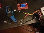
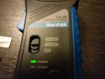
I have recieved my Oscilloscope , current clamp , 0.1 ohm 1% 3W resistor and some diodes an other things , but i have not received the dc-dc driver .

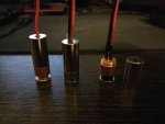
Diodes are : M140 (G2 lens) , BDR09 ( The one that was in the module) ) and Mitsubishi ml501p73(3 elements lens)
IMG_20181130_175116.jpg


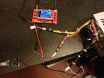
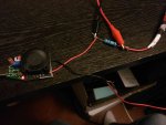
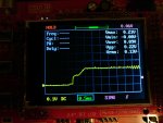
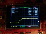
I tested the dso and current clamp with a 5v load with adjustable current(set on 2 amps) and a pc psu :

-With 0.1ohm resistor :
IMG_20181130_171251.jpg
IMG_20181130_171350.jpg
IMG_20181130_171316.jpg

-With Current clamp :
IMG_20181130_172001.jpg
IMG_20181130_171703.jpg
IMG_20181130_172017.jpg

The result are very similar. There is less noise with the 0.1 resistor .
Now i need to test on those dc-dc driver (the LM2596 driver and the XL4015 driver) when they arrive ...
 
Last edited:


Top