Welcome to Laser Pointer Forums - discuss green laser pointers, blue laser pointers, and all types of lasers

Buy Site Supporter Role (remove some ads) | LPF Donations

Links below open in new window

FrozenGate by Avery

electrical resistance of the battery's spring contact

Resistance in mechanical contacts like battery springs, but also switches and plugs, is always a tricky thing. One important factor is contact pressure, i.e. it helps if there is a lot of force pressing down on the battery.

On higher currents (over, say, 1 amp) its not unusual for the contact resistance to be quite high when you just insert the battery, but it will get much lower once you turn the device on. The contact resistance causes local heating which can sometimes more or less solder itself in place. This usually isnt visible or noticable when you remove the batteries, but it does happen on a microscopic scale.

You can try measuring the resistance before and after turning the laser on after you inserted a new battery.


I'm not going to start a new thread as this already exist, however I will say that it's true, a thin tail cap switch spring can add resistance.

I use little LED voltmeters on some of my builds and the 3 cell units don't mind some extra resistance, but the 2 cell units really show battery sag, I have upgraded tail switches and just adding a ring of solid core copper wire, such as 14 gauge or 18 gauge fashioned into a circle and soldered to the spring end really helps with contact area.

Some switches are not up to the load and burn out, but others work fine yet it seems all Chinese flashlights get cheaper and cheaper as for build quality as any given model ages and the price drops, yes we see Chinese copies of Chinese items, LOL.

Anyway the switch can be a weak link that cuts into runtime with high drain use, it's often worth it to beef up the switch and surprisingly just the contact area is an issue...well it can be but certainly not always.

Again this is not a big deal in many cases unless you are trying to minimize size and use smaller/less cells, then everything in between should be given an advantage such as battery spring contact area as it can make a noticeable difference in voltage drop.
 
Last edited:
Using a constant current driver will not help if the resistance is so large insufficient power can be supplied to that driver - it can't make power out of thin air.

But even if the driver is able to compensate, you'll lose battery life time due to power dissipated in the switch or other contact resistances.

And this can be a problem, i've seen laser pointers with momentary pushbuttons rated for 50 mA drive circuits that require 200 mA or more, and with the 'clicky' tailcap switches it can be even worse. Ramming a couple of amps though a switch rated for 200 mA isn't a good idea - you'll probably lose power in it, or in worse cases it will weld itself closed or break open permanently.

If you got a chance to design the entire thing from scratch, i would not even put the switch in the main current pathway, but use a low power switch instead, completing the circuit using a mosfet that has a much lower 'on resistance'.

Springs can be a problem too: those are usually made from steel, which is a fairly poor electrical conductor.
 
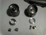
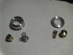
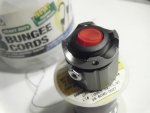
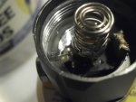
The factory switch spring pushes into that brass bucket and on the original MX-900 was a pretty solid arrangement with good surface area contact, the newer ones are not as good and with high loads the spring gets weak and my in unit volt meter shows a significant sag that is remedied with a refurbished switch or a solid jumper wire, poor contact points get hot, neo magnets can get hot so I don't use them anymore, I solder and sand a solder blob on top of the battery.

Also the old switch cap and FL tube has different threads than the new switch cap.

I just use a better switch and a good spring, I use gorilla brand hot glue to keep the switch in place.

Hey, it works.

If you feed the driver you should get WOW power until everything is hot and needs to cool down.

I'm not remembering who's video I saw, but I have seen some NUBM44's running the SXD @ 4.5a and they focus down any of our off the shelf lenses and make smoke on wood and paper/cardboard at point blank, that's not full power, at 4.5 amps a 44 with any off the shelf lens should spit fire at point blank, readily and repeatedly.

:beer:

The old solid is on the left, even the brass bucket is flat where the new one is pointed.

55482d1490686693-electrical-resistance-battery-s-spring-contact-sany0550.jpg


55483d1490686693-electrical-resistance-battery-s-spring-contact-sany0548.jpg


55484d1490686693-electrical-resistance-battery-s-spring-contact-sany0547.jpg


55487d1490686693-electrical-resistance-battery-s-spring-contact-sany0542.jpg


55485d1490686693-electrical-resistance-battery-s-spring-contact-sany0546.jpg


55486d1490686693-electrical-resistance-battery-s-spring-contact-sany0544.jpg


55488d1490687792-electrical-resistance-battery-s-spring-contact-sany0554.jpg
 

Attachments

  • SANY0550.JPG
    SANY0550.JPG
    177.7 KB · Views: 114
  • SANY0548.JPG
    SANY0548.JPG
    170.1 KB · Views: 110
  • SANY0547.JPG
    SANY0547.JPG
    169.7 KB · Views: 99
  • SANY0546.JPG
    SANY0546.JPG
    197.1 KB · Views: 98
  • SANY0544.JPG
    SANY0544.JPG
    199.3 KB · Views: 94
  • SANY0542.JPG
    SANY0542.JPG
    178.6 KB · Views: 98
  • SANY0554.JPG
    SANY0554.JPG
    181.9 KB · Views: 97
Last edited:
poor contact points get hot, neo magnets can get hot so I don't use them anymore, ...

This is why you should not use Nd magnets as contacts in high current applications: They are usually coated in nickel which is a decent conductor, but may still get warm when you're trying to run several amps through something like an 8 mm coated disc.

Most Nd magnets use magnetization somewhere between 60 and 100 degrees celcius, after which they are nothing more than a ceramic spacer with a thin nickel coating on them - the magnetic material itself is not electrically conductive at all.

You can easily test this by dropping such a magnet in boiling water - once it all cools down it's likely be demagnetized. Obviously you cannot solder onto them either (they 'take' solder fine but are not magnetic anymore after you are done).
 
I was not happy with these MXJO batteries in a 2 cell build because they were dropping from 8.3v at a full charge down to 7.6v and falling, but after replacing my tail switch and using a good spring with plenty of contact area, plus using the solder blob sanded flat against a piece of sandpaper to keep the spring on each end compressed and applying tension my fully charged pair drop from 8.3 to 8.05 and hold much better, it really can make a difference.

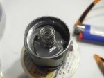
My issue was the factory tail cap spring under the bucket getting weak and because of my digital meters I have been installing I could see the spring going bad.

I will never use neo magnets, the solder blob sanded flat works great.
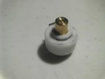
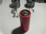
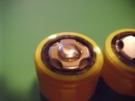
I clean the top of the battery and get a hanging solder blob on my big soldering gun, then scratch it into the center of the battery top and feed in solder to get the size blob I want, let it solidify and check it for strength ( They always bite in good ) then sand the top flat against some sandpaper laid on a flat surface. I use gentle controlled strokes keeping the battery perpendicular to the sand paper laid on a flat surface, works great.

55501d1490842662-electrical-resistance-battery-s-spring-contact-sany0559.jpg


There are all kinds of battery springs for sale on ebay, I wonder how much difference the beryllium copper makes over the nickel coated steel?

battery spring | eBay
 

Attachments

  • SANY0559.JPG
    SANY0559.JPG
    171.1 KB · Views: 90
Last edited:
The latter is hard to say - the total resistance depends on both the conductivity of the spring (easily calculated) and the contact resistance to the battery terminal (hard to estimate).

The copper, for example, is a very much better conductor than the steel, but it also oxidizes (and sulphates) more readily than the nickel coating on the steel. So initially the copper might perform better, but over time the nickel plated steel may prove more reliable.

Solder blobs make good contact points because the material is so soft any rotation or compressive forces will expose fresh metal without an oxide layer in the way. Other than that, solder actually is a pretty poor electrical conductor.

The other extreme is aluminium which is an excellent electrical conductor, but very hard to work with since it forms a very hard isolating conductive layer on it's surface.


Back
Top