Welcome to Laser Pointer Forums - discuss green laser pointers, blue laser pointers, and all types of lasers

Buy Site Supporter Role (remove some ads) | LPF Donations

Links below open in new window

FrozenGate by Avery

ECDL setup with custom controller

No you missed the point. Errors are not all the same. Typographical errors are not spelling errors. And words that sound the same, but are not aren't either. I've already explained myself on this. Just can't let it go can you?


No you missed the point. Errors are not all the same. Typographical errors are not spelling errors. And words that sound the same, but are not aren't either. I've already explained myself on this. Just can't let it go can you?
Paul you're hopeless
 
You entirely missed the point that you criticized someone for an error but then proceeded to make them yourself.

Unown..... You gave me a " Time out " for doing exactly what you are doing right here. Going back and forth with paul, even though it was on the thread topic. As a moderator you should be above attacking typos when you are so hypercritical of others. You should not be instigating/attacking.

If you point out a typo then you should spend ( 1 ) sentence to do it politely and then no more, as a proper authority figure.

And you should never, block someone for pointing out your obvious shortcomings, you should say ( Thank you ) and correct the behavior.

If you block me for saying this I will contact Avery and I hope everyone else will too. A moderator should not be a bully !
 
Last edited:
Unown..... You gave me a " Time out " for doing exactly what you are doing right here. Going back and forth with paul, even though it was on the thread topic. As a moderator you should be above attacking typos when you are so hypercritical of others. You should not be instigating/attacking.

If you point out a typo then you should spend ( 1 ) sentence to do it politely and then no more, as a proper authority figure.

And you should never, block someone for pointing out your obvious shortcomings, you should say ( Thank you ) and correct the behavior.

If you block me for saying this I will contact Avery and I hope everyone else will too. A moderator should not be a bully !
This coming from someone who wants Paul permabanned. Honestly don't know why you're adding to this pointless argument. You were temp banned for posting seriously inappropriate gifs. I mean you are in no position to start lecturing.
 
Sorry, after beeing a long time a scielent reader, I have to put my 50¢. By posting a how to build an ecdl was done 10000 times.

Better than you could here. No results so far, but a lot to say. Modulating the laser within the cavity will give you the most side peaks at the FSR, but this is not a pulsed or a mode locked laser.

Singlemode
 
The roundtrip time of this resonator is around 250 ps so 10+ GHz photodiode would useful for analyzing pulse forming in external cavity (but that's foreshadowing future events 😊 ). I have access to 28 Ghz 4 channel oscilloscope, so that's not an issue. The best I could find that don't cost an arm and a leg have bandwidth of 3 Ghz max, so I may have to extend cavity length. This would be unfortunate for pulsed experiments though (more foreshadowing).

I can't dig up papers right now, but basically modulating a laser diode with RF at close to cavity round trip time can create spectrum similar to mode locked lasers.

If your cavity is 100mm long, then your fsr is 1.5GHz. not 10GHz. This is easily detectable by a standard pd with a bias and an RF amp.
 
If your cavity is 100mm long, then your fsr is 1.5GHz. not 10GHz. This is easily detectable by a standard pd with a bias and an RF amp.
FSR is 1.5GHz (as you can see I put round trip ~250ps) but to analyze pulse evolution in laser cavity you need much higher bandwidth thanks to highly nonlinear effects in the resonator:

Sorry, after beeing a long time a scielent reader, I have to put my 50¢. By posting a how to build an ecdl was done 10000 times.

Better than you could here. No results so far, but a lot to say. Modulating the laser within the cavity will give you the most side peaks at the FSR, but this is not a pulsed or a mode locked laser.

Singlemode
You can get mode locking in ECDL under certain conditions:

Thank you for the "constructive" criticism. If you'd like to add something more, you're very welcome.
 
Last time I wrote introduction post about optics in the ECDL. Now let's talk about custom driver designed for it. The driver has to do the following:
  1. Provide low noise, constant current for driving laser diode
  2. drive two Peltier modules with sufficient resolution
  3. Measure temperature of important elements
  4. stabilize the temperature inside the cavity
  5. have some easy adjustment and monitoring
For simplicity, I opted for digital solution. TEC, thermistors and LD river are connected to microcontroller that implements all control algorithms. It also allows to easy adjustment of operating point over USB.


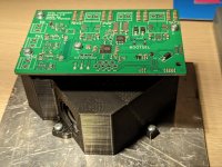
I also printed first, prototype enclosure. Full device currently looks like this:
As always more technical details can be found on my blog: https://sduc6.blogspot.com/2024/04/external-cavity-diode-laser-part-2.html
ECDL_preliminary_print.jpeg
 

Attachments

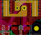
  • ECDL_LD_driver_layout.png
    ECDL_LD_driver_layout.png
    60.3 KB · Views: 4
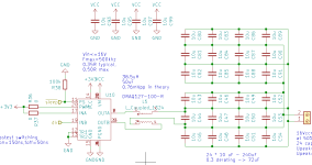
  • ECDL_TEC_driver.png
    ECDL_TEC_driver.png
    25.7 KB · Views: 3
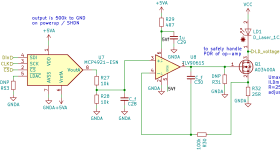
  • ECDL_LD_driver.png
    ECDL_LD_driver.png
    26 KB · Views: 4
Last edited:
FSR is 1.5GHz (as you can see I put round trip ~250ps) but to analyze pulse evolution in laser cavity you need much higher bandwidth thanks to highly nonlinear effects in the resonator:


You can get mode locking in ECDL under certain conditions:

Thank you for the "constructive" criticism. If you'd like to add something more, you're very welcome.


Google for 497nm ecdl (Arxiv). They have the simplest design ever and still running at NASA/JPL.


Singlemode
 
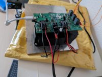
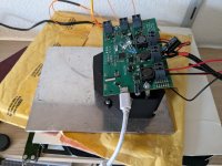
Let's talk more about the controller. After a lot of code writing, I managed to power up almost everything and even implement the simplest possible control loop. Everything is controllable over USB with VISA and all settings are persistently stored in flash. All the bookkeeping (usb, interrupts handling, fault monitoring, etc) is running on core 0 with core 1 fully dedicated to (future) control loops.

All analogue hardware is fully functional, though with slight changes from the original:
  • the MAX6035 reference source has been substituted for a cheap 5V regulator. It turns out that thermistors' analogue chain have enough PSRR to work properly even with not as well regulated ref voltage, saving around $3 per board. The slight downside is that laser diode accuracy dropped slightly.
  • Feedback resistors around op-amp had to be increased to increase noise level to ~1LSB
  • 1500uF bulk capacitance had to be added on power rail to absorb reactive power from switching TEC outputs quickly.
And now what everyone is waiting for - real world performance measurements:
  • The laser diode constant current source is quite bad with 0-100mA range, 0.2mA precision and accuracy of around 2mA. That was expected as I don't need to set specific current often, but I need to adjust it quite precisely to hit centre of SM operation
  • The thermistor paths at the beginning had true 16 bit performance, but that makes averaging ineffective, so I increased noise until the histogram showed a standard deviation of 1.1LSB. The ADCs run at 50ksps and are downsampled 512 times, theoretically giving another 4 bit resolution boost. With current analogue gain, the resolution hovers between 0.4 mK and 0.6 mK in >40 K range. The accuracy is bad, around +-1K but that's not important for ECDL and can be compensated using 4 point calibration
  • The Peltier modules are driven with a combination of PWM and sigma delta modulation. To get a good filtering, PWM has to run above 50 kHz, limiting resolution to around 8 bits. On the other hand, sigma-delta modulation requires a lot of transitions that generate too much switching loss. The solution used here is PWM that is switching between two values every period, with switching distribution selected by sigma-delta. It's not an optimal solution for minimizing in-band noise for a given set of edges at a given clock speed but it's quite close, and it's computationally efficient thanks to DMA
In the steady state, the system wanders around 1mK on both temperature sensors. When I've put ice cubes on outer baseplate the inner baseplate temp changed by 100mK max and LD temps changed by 20 mK max (with barely tuned PID loops).

Now it's time to implement MPC and autotuning. In the meantime, here are some more pictures for you all to enjoy:
 

Attachments

  • signal-2024-07-13-195603_002.jpeg
    signal-2024-07-13-195603_002.jpeg
    864.8 KB · Views: 1
  • signal-2024-07-13-195603_003.jpeg
    signal-2024-07-13-195603_003.jpeg
    1,010.5 KB · Views: 1


Back
Top