Welcome to Laser Pointer Forums - discuss green laser pointers, blue laser pointers, and all types of lasers

How to Register on LPF | LPF Donations

DX 35mw Labbie Green

Jules

0
Joined
May 26, 2008
Messages
89
Points
0
I just got mine, I am at work and can't power it up. Couple observations:
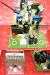
The PSB shows AC input and those leads go straight to a bridge diode on the board. There also appears to be two complete sections. One for Red one for Green. Outputs to the Laser module show a green connector and a red connector. The connector to the diode module is "siliconed" on. There are also TTL inputs for both Red and Green. Has anyone else noticed this? The focus ring has silicone on it which should be easy to remove. I already took the silicone off of the current adjust potentiometer. The Laser head is hand labeled with a current of 380ma (Which I assume is the internal IR diode) there is a spot to check off on the laser warning label for laser output but nothing is checked.

Can't wait to get home and power it up! This is going in my scanner, which of course I have not started yet

Jules
 

Attachments

  • DX35mwLabieGreen.jpg
    DX35mwLabieGreen.jpg
    170.1 KB · Views: 240


OK, I am looking for a little help here.... I applied power (6VDC) saw the red LED on the circuit board come on, but no output. Also no real current draw from the power supply. Does anyone know how the TTL part works? do I need to apply a +5 VDC to the Green TTL input to get it on? Heading to Deal Extreme right now to see if I am missing something...
 
that's what you got for the 35mw green? looks nothing like the two i have (35mw and 50/100mw versions)
 
Yea, the people reviewing said that what they received looked nothing like what is on the web site. I am going to try hooking up 6VAC to it later tonight. Got to attend to the wife and kids till the kids go to bed... LOL!
 
Here you go. I got it working. (Woo Hoo) The damn connector to the Laser module is intermittent. THank god it didn't fry the diode. You have to hold it a certain way. I am going to solder it to the PCB when mounted. Note the connectors for the Red AND the green. Two adjustment Pots etc.

Jules
 

Attachments

  • DX35mwG1.jpg
    DX35mwG1.jpg
    659.9 KB · Views: 279
Picture Number Two
 

Attachments

  • DX35mwG2.jpg
    DX35mwG2.jpg
    536.4 KB · Views: 545
Thats strange, looks nothing like the one I had, I better not get that one as a replacement >:( The PCB and the module are both different .
 
Scratch that, the module actually looks similar, but that front bit is screwed right in, I was aware that it was a lens, maybe these are focusable, and we just never noticed :-?
 
MarioMaster said:
yeah, the actual laser module looks like the 50/100mw one i have, but the pcb doesn't match either one

here's the review i did of mine http://www.laserpointerforums.com/forums/YaBB.pl?num=1200717134/0

Your review is what prompted me to buy one! Thanks! As everyone has noticed the PCB I got does not match what others received. Gotta Love Deal Extreme. This weekend I plan on working more with it and will post my findings. I am going to put this into a scanner/show setup with a couple dichro's and try and get a Red Green 405 thing going.

Love this Forum.
 
lol good, if only you had a power meter, maybe this one outputs differently, I'll bet the current is different too.

Diachi
 
Yea, I wish I had a power meter. What is a good cheap one? I plan on setting it up so I can measure the current going into the module. The module is hand labeled 380ma. I am probably going to bring it up to 500ma and see what happens. I am also gong to experiment with focus adjustment on the lens. Gotta burn something... Isn't that what lasers are for?
 
Just got my replacement and it doesnt work, same problem that jules had, I'll try soldering it to the PCB and see if that works :-/
 
SHE LIVES, just fired it up there and wada ya know, green :D Just need to solder the leads on to make the connection more permanant :D


Back
Top