Welcome to Laser Pointer Forums - discuss green laser pointers, blue laser pointers, and all types of lasers

LPF Donation via Stripe | LPF Donation - Other Methods

Links below open in new window

ArcticMyst Security by Avery

DT-25 scanner connections to DAC

Jaseth

0
Joined
Jan 30, 2009
Messages
1,630
Points
0
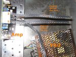
I bought some DT-25 scanners not too long ago and I am getting everything wired up to my FB3.
I am very cautious with electricity as I don't want to get a shock and I don't want to fry this expensive equipment. It would be great if anyone could help.

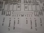
Which wire is which on the signal connector between the amp and DAC (the ones which are connected to the same slot as the power supply for the amps)?
I have 3 wires running from each part of the amp:
One with thin stripes across,
one dotted,
one with fat lines running along the length of the wire.
I looked in the manual but it did not describe which is which.
My guess is that "Fat Line" is positive, "Striped" is negative and "Dotted" is ground/earth. Perhaps the last wire is not even ground/earth but something completely different..
Amp output Y is marked 1 and amp output X is marked 2.
I have marked each of the wires.
I just want to be completely sure before I connect these.

Thank you in advance,
Sebastian
 

Attachments

  • IMG_1226.JPG
    IMG_1226.JPG
    129.1 KB · Views: 273


Joined
Nov 7, 2008
Messages
5,725
Points
0
Those wires look different than scanpros.. I'd try trial and error. You're not going to hurt those amps if the incoming signal from the DAC is wrong. The output just won't look quite right. The connections that you need to worry about being correctly polarized are the power supply connections. If they're wrong, damage will result.
 

Jaseth

0
Joined
Jan 30, 2009
Messages
1,630
Points
0
Thanks! I did the power supply as L=brown, N=blue and Ground=green. I am sure this is correct.
I will go ahead and try.. Any idea what the wire which is not Positive or Negative will be?
I was guessing it might be Interlock A and B or just the ground as shown on the ILDA Pinout here:
 

Attachments

  • RGBpinout.png
    RGBpinout.png
    15 KB · Views: 539
Joined
May 24, 2007
Messages
3,394
Points
0
read the manual

there will be a ground, X - & + and Y - & +

the 6th may not be used
 

Jaseth

0
Joined
Jan 30, 2009
Messages
1,630
Points
0
The manual only says:

"Next, connect the signal cable from your DAC to the DT-25 Amp. The following image shows how the X and Y signals are connected to the Amp. As per the recent recommendation by Bill Benner of Pangolin, leave the ground cable unplugged. Instead attach the ground from your DAC to the power supply ground."

But the image provided does not show the connection to the DAC; only the connection of the wires to the amp, which is already seen in the picture I myself attached.
Thank you for confirming that the last wire is ground!

Seb
 

Jaseth

0
Joined
Jan 30, 2009
Messages
1,630
Points
0
:bumpit:
I have tried all combinations of connections and I still do not get anything else than a horizontal or vertical scan line. I hope I haven't broken something.
 
Joined
Nov 7, 2008
Messages
5,725
Points
0
I don't have an FB-3 so I really don't know exactly how they should be connected.. It's odd that the DT-25 instructions don't show you which connections on the amp board are positive,negative and ground. My scanpro manual shows the layout of the actual PC-board itself and each connector is labeled pin by pin. The outputs of your FB3 should also be clearly labeled.
 

Jaseth

0
Joined
Jan 30, 2009
Messages
1,630
Points
0
Really the only instructions I have are some I had to find myself on the internet, and they do not describe anything about wires or pins. They tell you to connect them, but not which wire to which output or input. I already had to spend about 1 hour making sure I was connecting the power supply properly because there were not instructions for that either, and no included cable.
I am getting rather frustrated and Rob from laserwave has not been answering for a couple of days..
 
Joined
Nov 7, 2008
Messages
5,725
Points
0
I just took a close look at your pic and it stands to reason that the polarities will be the same for the DAC signal as they were for the power wires in between them.. Whichever of the power wires was ground (stripe, dashes, etc..) will most likely also be ground on the amp connections and so on..
 

Jaseth

0
Joined
Jan 30, 2009
Messages
1,630
Points
0
Yes that was what I thought would be the explanation, but all the wires seem to be different.. X amp wires, Y amp wires and power wires all react differently. I haven't seen anyone else ever ask about this problem. I am stuck after 4 hours of research on the internet, 1 hour of trial and error and several days of asking for help here, on PL and from the dealer. I was so excited about this but nothing seems to work. :(
 
Joined
Nov 7, 2008
Messages
5,725
Points
0
All I can tell you then is to be patient and wait for a response from the vendor.. Don't work on it if you're too frustrated, you'll only mess it up.
 

Doc

0
Joined
Aug 14, 2008
Messages
35
Points
0
Here's the instructions with photos
 

Attachments

  • DT-25 User Manual.doc
    858.5 KB · Views: 3,781

Jaseth

0
Joined
Jan 30, 2009
Messages
1,630
Points
0
That is the manual I have already found myself.
The problem is at point 5 where the photo shows the "X signal cable" and "Y signal cable" but nothing about what each of the wires in the cable should be attached to.
 

DJZ

0
Joined
Aug 27, 2008
Messages
270
Points
0
Hi Jaseth, have you tried to contact the person you purchased these from? I'm put together the user manual, which was rather hastily done I admit! Anyway, take a look at the photo attached, on the amp board itself, you can see, starting from the right, +Y -Y and what looks like a side ways "T". The side ways "T" is ground for the incoming signal from the FB3, this you can actually leave disconnected IF you have properly grounded the DT-25 power supply. Same thing on the other side of the connector, starting from the edge, you have +X -X and the side ways "T". So all you need to do is attach +X -X +Y -Y to the FB3. If you have no ouput from the scanners, then you might have an FB3 which only outputs single ended, if this is the case, then the next possibility is that the gain on the amp is set to 0. The two pots closest to each other can be adjusted until you have scanning.
 

Attachments

  • DSC09788.JPG
    DSC09788.JPG
    81.4 KB · Views: 249
  • DSC09790.JPG
    DSC09790.JPG
    61.7 KB · Views: 206

Jaseth

0
Joined
Jan 30, 2009
Messages
1,630
Points
0
Sorry for the late reply, I graduated a few days ago so I have hardly been at home at all.
Firstly thank you for the user manual, apart from that single thing it explains everything very well.
Secondly, thank you SO much for your help! My eyesight is not good enough for me to see such tiny letters but now with your explanation and picture I have found the correct connections using a magnifying glass.
Perhaps you should add the picture to the manual in case future customers have bad eyes? :)

Anyway, I cannot thank you enough. My scanner is soon finished!

Seb


Top