Welcome to Laser Pointer Forums - discuss green laser pointers, blue laser pointers, and all types of lasers

LPF Donation via Stripe | LPF Donation - Other Methods

Links below open in new window

ArcticMyst Security by Avery

Driver with voltage controlled output

Joined
Oct 22, 2011
Messages
14
Points
0
Hi guys,

Im interested in an efficient (so not linear) driver which can be current output adjusted via an external voltage (from a buffered DAC).
In my device, the power is supplied by 2 parallel 10440 cells, so 3,7V in. I want to drive an Oclaro HL63193MG, so voltage around 2.6V and current should be adjustable between 250mA - 1.2 A (or more?). Probably, a buck/boost driver is needed.
Do you know if there is a driver out there which can be used here (or which can be modded)?
I am experienced in soldering small SMD components, so I'm not scared of changing existing drivers.
I hope you can help me :)

Best regards,
Nikolas
 
Last edited:


Joined
Oct 22, 2011
Messages
14
Points
0
Some additional information (in a seperated post so the opening post does not derail too much):
I know that most (or all) switching drivers compare some feedback voltage to their internal error voltage and here I can basically modify the driver with an external signal.
I developed 2 different Aixiz-size drivers myself (with 2 different approaches) and tried this. I found that stability for these drives is a huge issue. One of my attepts seemed to work but killed the diode several days later (and I still don't know exactly, why).
Don't get me wrong, I don't need fast response. The signal is in the Hz range, so for the usual switching frequencies of drivers, it looks almost like DC.
I looked at the schematics of the Dr.Lava flexdrive and found that just adding some voltage to the pot does not yield the wanted result.
So did anyone here ever tried something like this? Or is PWM the only option when it comes down to regulating a laser output?

Best regards,
Nikolas
 
Last edited:
Joined
Sep 20, 2008
Messages
17,622
Points
113
You haven't mentioned if your setup has a
size constraint...
Have you tried Google...:thinking:
I believe someone posted a schematic of
something similar on the Forum at one time.

BTW... Double Posting within a short time is
frowned upon by the Forum Community.
It is easy to combine or edit your posts by
using the [EDIT] button at the bottom right
of any of your posts.


Jerry
 
Last edited:
  • Like
Reactions: GSS
Joined
Oct 22, 2011
Messages
14
Points
0
I don't have a usual aixiz module size constraint. But it still would be handheld, so no desk-supply or something like this. Lets say maximum around 4 times the size of a usual aixiz-size driver. I searched the forum and found an old post, but it was not helpful in my situation. Perhaps my googeling skills are bad, but I didn't find a solution there. The answer is always: use PWM.
I really want to be efficient, a simple linear approach is not an option.

Sorry, I knew that doubleposting is not the usual way, but I wanted to keep the original post short. I promise to not do it again :angel:
 
Last edited:
Joined
Sep 12, 2007
Messages
9,399
Points
113
The feature you want is known as analog modulation. Here's the go-to product that is capable of this. It is also coincidentally designed by Dr Lava.

https://innolasers.com/shop/index.php?id_product=11&controller=product

Of course, this is a linear driver. All analog modulation drivers that I've seen are linear, since switchmode drivers are not fast enough.

However, If you only need something in the Hz range, that could be done with existing switchmode drivers. In order to help further, I'd need to know the nature of your DAC setup.
 

Benm

0
Joined
Aug 16, 2007
Messages
7,896
Points
113
I suppose any driver could be used as long as it has a reference voltage that determines the current. You use the DAC instead of a voltage reference to provide the reference voltage, and you have control over the output current.

If you don't need fast response speed it would be advisable to use a RC network between the DAC and reference input of the driver to take away any voltage spikes that otherwise would be translated into current spikes on the output.

DACs can sometimes produce unwanted voltages briefly when controlled the wrong way, for example not having a good latch between inputting the value and setting the actual output. Say you'd want to go from 0111 to 1000 (just a single step on 4 bits), you could briefly make it output 1111 when writing the value if there is no latch.
 
Joined
Oct 22, 2011
Messages
14
Points
0
Hi, im Using the DAC output of an ATSAMD20E18 µC and a LT1797 as a simple impedance converter. I expected that a low pass filter would come in handy and there are unpopulated areas for this.
It would be nice if you guys could suggest a driver for my application which I can control in the suggested way, but from my knowledge, there is currently no good buck-boost out there besides the microflex. Perhaps you're smarter than me, I can send you (privatly) the schematics of the microflex if you're interested, so you can tell me how I can change this one.
 
Joined
Sep 12, 2007
Messages
9,399
Points
113
Okay, so the microcontroller is adjusting output based on what input? And why use a DAC when you could drive a digipot instead?
 
Joined
Oct 22, 2011
Messages
14
Points
0
I just want to have a manually adjustable laser output. So the driver should stabilize the current proportinal to an analog signal.
Digipot is a solution, although an ugly one; besides the adding of a board with only the digipot on it, digipots are limited in resolution of around 10 bit.
It seems so wrong to artificially change the circuit of a driver, when you could just influence the voltage feedback with a simple DAC.
 

Benm

0
Joined
Aug 16, 2007
Messages
7,896
Points
113
That, and many microcontrollers have the DAC's built in on several pins, so why no at least try to use what's available?

You could for example use the PWM outputs from an atmel chip (like the one on an arduino) to get to a usable analog signal. Since this is PWM and you want an analog voltage a low pass filter is essential, but as long as you don't need a high rate of speed that filter can consist of as little as one resistor and one capacitor.

You would probably need 2 resistors in any practical application as the microcontrollers runs up to 3.3 or 5 volts and the reference usually is something like 1.2 or 1.25 volts, but that's about all.

I'm not sure what commerical drivers would be best suitable for such a modification: most linear drivers would be very easy to convert, but the switchmode ones differ: some have internal references that set the output current by some resistor value tied to one of their pins, while others do use an external reference voltage (or can do so).

Form factor is an issue here though: many drivers are built to a very small form factor to fit hosts and modules, and those are more difficult to modify compared to something built with for a larger envelope.

Then again if you have plenty of space (like in a projector) there is no real need to fumble around with switchmode laser drivers at all, you can build them linear and heatsink properly. This may not be as electrically efficient but when it runs off the mains that's of little concern, and in my opinion worth the added flexibility and reliability.
 
Joined
Sep 12, 2007
Messages
9,399
Points
113
I just want to have a manually adjustable laser output.

So use a potentiometer in the feedback loop. Why would you insist on introducing additional circuitry like a microcontroller in the first place? You clearly have no idea how to implement it in the first place.

digipots are limited in resolution of around 10 bit.

1024 settings aren't enough? Do you honestly think you could tell the difference between 608mA and 609mA? Because you can't.

Why would you start the thread with this statement:

I'm not scared of changing existing drivers.

And then when offered a potential solution, say this instead?:

It seems so wrong to artificially change the circuit of a driver

DMDq5DL.gif


This is proof to me you're being disingenuous, arbitrary, and stubborn. I'm done wasting my time with you. Good day sir.
 
Last edited:

Benm

0
Joined
Aug 16, 2007
Messages
7,896
Points
113
There is little choice indeed, if you want to take an existing driver and add manual or digital control to that, you'll have to modify it.

One thing is that just modifying the reference voltage from a standard bandgap reference to a DAC output is not that -big- of a modification (i.e. remove 1 component and solder 1 wire on). On the other hand not all driver desings will allow control over the full range, so this can be a bit tricky and require some trial and error.

What i don't see is why you would need or use microprocessor control in such a small form factor though.
 
Joined
Oct 22, 2011
Messages
14
Points
0
@Cyparagon
I think you're judging me and my behaviour here a little too fast.
I know how to implement a digipot in a stock driver, in fact I designed yesterday an additional pcb in the form factor of the microflex to add just that. Why I add a microcontroller in the first place? Because my application is just a bit more sophisticated than a simple host for a diode.
Well, 1024 settings are enough in many situations, but some drivers are in the higher current region far from linear, and then the resolution is quite poor.
And you just misunderstood my last statement: As someone who designed several switch mode power supplies myself, I think the idea of injecting some voltage in the feedback loop is so much more straightforward than a digipot. In fact, my 2 driver attempts never had a problem with this part; it was more the stability of the feedback in general.
What I wanted to express is just: it is such a obvious solution for adding analog modulation to switchmode laser driver that I am pretty disappointed that no driver out there is capable of that, so I have to take the more complicated digipot solution.
It's sad to see such a judgemental and aggressive post in a polite and factual discussion.

@Benm
I see, we are on the same side here: using an already available analog output of your µC is the obvious solution for the problem. Linear is of course an easy way, but I want to stay efficient since I'm still battery powered.
Your second post comes back to my intial question: does somebody know a buck/boost driver which is can be modified to inject anlog modulation? The only buck/boost I found with adjustable input is the microflex. If it helps the discussion (and I don't commit a crime or something like that for doing so), I could post the schematics of the microflex so we can think about it together.
 
Last edited:
Joined
Apr 29, 2008
Messages
1,562
Points
48
@Cyparagon
I think you're judging me and my behaviour here a little too fast.
I know how to implement a digipot in a stock driver, in fact I designed yesterday an additional pcb in the form factor of the microflex to add just that. Why I add a microcontroller in the first place? Because my application is just a bit more sophisticated than a simple host for a diode.
Well, 1024 settings are enough in many situations, but some drivers are in the higher current region far from linear, and then the resolution is quite poor.
And you just misunderstood my last statement: As someone who designed several switch mode power supplies myself, I think the idea of injecting some voltage in the feedback loop is so much more straightforward than a digipot. In fact, my 2 driver attempts never had a problem with this part; it was more the stability of the feedback in general.
What I wanted to express is just: it is such a obvious solution for adding analog modulation to switchmode laser driver that I am pretty disappointed that no driver out there is capable of that, so I have to take the more complicated digipot solution.
It's sad to see such a judgemental and aggressive post in a polite and factual discussion.

@Benm
I see, we are on the same side here: using an already available analog output of your µC is the obvious solution for the problem. Linear is of course an easy way, but I want to stay efficient since I'm still battery powered.
Your second post comes back to my intial question: does somebody know a buck/boost driver which is can be modified to inject anlog modulation? The only buck/boost I found with adjustable input is the microflex. If it helps the discussion (and I don't commit a crime or something like that for doing so), I could post the schematics of the microflex so we can think about it together.

I would like to see a schematic of the flexdrive. I've been curious about how the flexdrive achieves buck/boost action with a 5-pin IC and no inversion. From there, I may be able to help!
 
Joined
Oct 22, 2011
Messages
14
Points
0
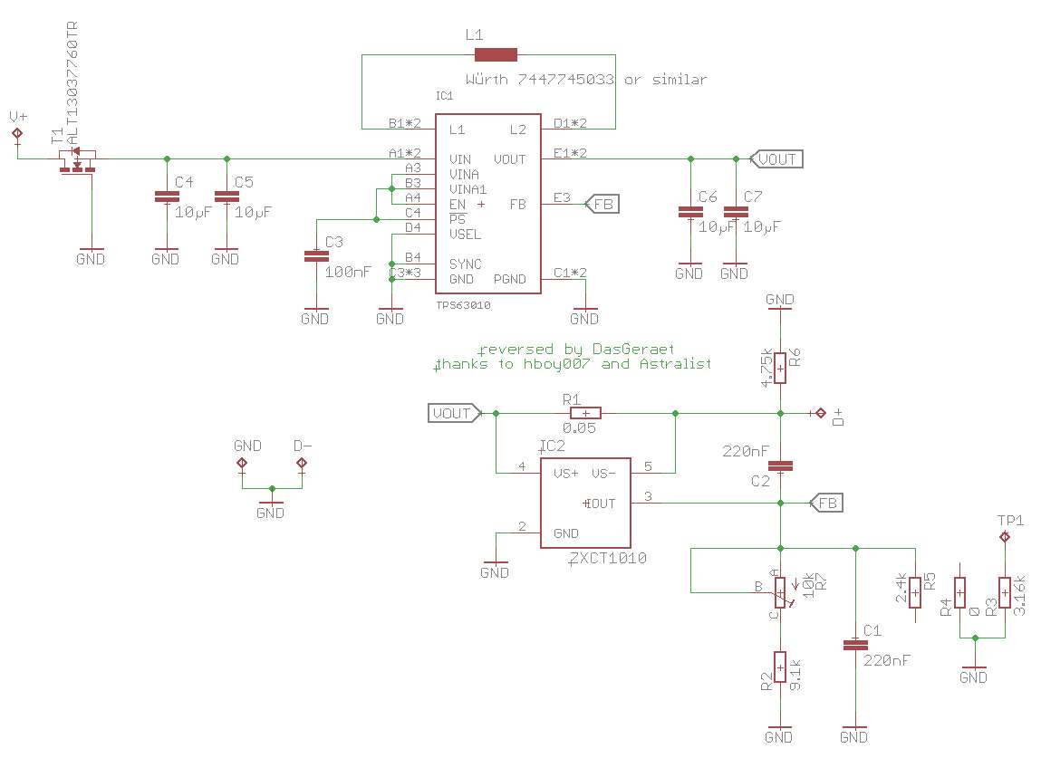
Here is the schematic of the Dr.Lava microflex drive V5:
ZcSvNF.png

R2,R3,R4 and R5 are the current output range select resistors.
Updated with the now correct CSM, thanks to Astralist.
 
Last edited:
Joined
Mar 27, 2011
Messages
507
Points
63
Btw, to prevent some headache and great effort, you can just use BlackBuck 8, it can be adjusted using analog modulation and has a dedicated pad to solder the modulation input.

See the information about BB8 somewhere in her or ebay.


Top