Welcome to Laser Pointer Forums - discuss green laser pointers, blue laser pointers, and all types of lasers

Buy Site Supporter Role (remove some ads) | LPF Donations

Links below open in new window

FrozenGate by Avery

Driver Test Load for PHR-803T Schematic

The Negative of your battery is your ground....:cool:

For the 99pc 1 Ohm resistors...You could sell them to members here
to build their own Dummy Loads... and you could maybe even include
6 diodes....:whistle:


Jerry


These things are best bought in quantity, keep the leftovers for another project.

You could have just used the 10 ohm resistor and one or two less diodes - might even make a better model of the blu ray diode up to 200 mA or so. It would read 10mV/mA then, but thats easy enough.
 
ill show a picture of everything connected when i get a driver
 

Attachments

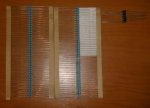
  • 1N4001 Diodes and 1 Ohm 1% Resistors.JPG
    1N4001 Diodes and 1 Ohm 1% Resistors.JPG
    29.5 KB · Views: 401
I'm almost sure 1% tolerance resistors do exist, I would go for one of these since you only gonna need one for all your lasers :P

Also, maybe using 4 resitors in this way: 2 in parallel and in series with 2 more in parallel would not only increase the power they can hold but also the precision :D
 
I have seen many dummy loads, Ans some seem that contradict one to another. What goes first at the output of the positive of the driver, does the 1 ohm resistor or the 1N4001 diodes go first?
And to what direction should the white bands of the 1N4001 diodes should go?
Maybe i have something wrong in my diagram
I want to correct before someone do it wrong because of me.
 
It doesn't matter where the resistor is, it could go either end or even between diodes it would do the job.

First picture shows a test load set up to do either red or blu-ray. Note direction of white stripes on diodes and colour coded pos and neg wires.
Second picture shows how to test an IR (as used in green) laser diode.

The alternate place for the 10hm is if you want to test current draw with the laser diode soldered to the driver.

Regards rog8811
 

Attachments

  • test load01.jpg
    test load01.jpg
    41.2 KB · Views: 874
  • testing green driver.jpg
    testing green driver.jpg
    31.2 KB · Views: 2,197


Back
Top