Welcome to Laser Pointer Forums - discuss green laser pointers, blue laser pointers, and all types of lasers

Buy Site Supporter Role (remove some ads) | LPF Donations

Links below open in new window

FrozenGate by Avery

Driver Specifications Compendium

Unfair IMO calling this a necro--many still have ALL/some these drivers and need to know the info.
I just came across a dozen rckstr drivers and need info to use them.


Well, this one is still here and I doubt anyone is going to change/delete it. For ones that are still available as new stock items, a new thread would probably be easiest and wouldn't change anything already posted. I, for one, would like to see a new thread with all the new available drivers with their specs and particulars included.
 
there are so many many drivers available
Definitely , no way ill be sifting through the ebay listings, as most of the driver are most likely constant voltage.

First of all, thanks for undertaking a thread like this, an updated, or new driver thread would be very appreciated, also, you should be able to attach as many photos as you want to each post; as an example, trevors post #1 in this thread contains 17 different driver pics.
The only thing I can think of that would limit you is if you're using thumbnail pics or something I'm not familiar with. :)

No problem :beer: I've already got the info together just need a relativity easy method to write it into a LPF thread.

As for the photos, i think Trevor has his linked from an external source, on the new thread page, it only allows 7 boxs to be filled with a pic or file / per post.

Unfair IMO calling this a necro--many still have ALL/some these drivers and need to know the info.
I just came across a dozen rckstr drivers and need info to use them.

Who said it was necro? I believe its not possible to necro-post in a Stickied thread......it a sticky for a reason.....its meant to last, be updated and easily refered back to throughout time :D

I just recently attached a Rckstr driver to a 808nm diode, it was like time travel :crackup:

SO....ill try an get a new thread up, and we can play with its format to create a thread we can all benefit from :beer:
 
So just a quick question for my community here. My understanding is that buck/boost or buck or boost or linear drivers have all their back draws. From what I've studied and understand it's never smart to run just a buck or boost or linear driver(without thermal runaway protection)(( but no bucking abilities,)) to power a diode. Buck/boosts get alot of EM interference and they give off alot of ripple you won't see in controlled testing,(like if someone was dropping them or using them by other electronics or magnets or what have ya) that'll destroy or greatly shorten the life of your LDs. Linear drivers are great with thermal protections but no modular ability as the buck/boosts... I've been trying to see about combining a buck/boost with a linear all into one to eliminate all the weaknesses of the drivers themselves, I just know this will probably increase the overall circuit drain by dang near 2v which is alot if you also need 2v for the buck/boost half. (or 1.5 respectively) ... Yeah.. been struggling with this. Trying to prototype a project and need a driver but can't decide on any good ones as they all fail on requirements.. but my circuit designs skill is 100% garbage so.. *pulls hair out* lol. I need to power a up-to 2W LD(probally blue nm, not sure why that matters on all these drivers? like whys the color matter? its just C-current?) for long and efficiently and safely as possible. Scaling between 100ma and 1.6a max.(don't wanna push the full 1.8a or 2a not necessary =p) and not decided on a battery yet, but it needs to fit into a fairly small space (only about 2 AAs worth of space or so).. I more then welcome any thoughts or recommends on this?
 
for the seeing disadvantaged..let me unbrick that for you...


So just a quick question for my community here.

My understanding is that buck/boost or buck or boost or linear drivers have all their back draws. (drawbacks)From what I've studied and understand it's never smart to run just a buck or boost or linear driver(without thermal runaway protection)(( but no bucking abilities,)) to power a diode.

Buck/boosts get alot of EM interference and they give off alot of ripple you won't see in controlled testing,(like if someone was dropping them or using them by other electronics or magnets or what have ya) that'll destroy or greatly shorten the life of your LDs. Linear drivers are great with thermal protections but no modular ability as the buck/boosts... I've been trying to see about combining a buck/boost with a linear all into one to eliminate all the weaknesses of the drivers themselves, I just know this will probably increase the overall circuit drain by dang near 2v which is alot if you also need 2v for the buck/boost half. (or 1.5 respectively) .

..... Yeah.. been struggling with this. Trying to prototype a project and need a driver but can't decide on any good ones as they all fail on requirements.. but my circuit designs skill is 100% garbage so.. *pulls hair out* lol. I need to power a up-to 2W LD(probally blue nm, not sure why that matters on all these drivers? like whys the color matter? its just C-current?) for long and efficiently and safely as possible.
Scaling between 100ma and 1.6a max.(don't wanna push the full 1.8a or 2a not necessary =p) and not decided on a battery yet, but it needs to fit into a fairly small space (only about 2 AAs worth of space or so).. I more then welcome any thoughts or recommends on this?

______________________________________
...@the OP-- we have had to deal with MUCH larger bricks,,hahha
so dont feel bad..hak
 
Actually, Len, color does matter. The red diodes all have very low forward voltages, the blues....in the middle, and the greens are fairly high. This will determine if you use a buck or a boost driver in many cases. As you know, some are better drivers than others are. For a 2 watt blue, I'd likely use a good SXD or X-Drive with two Li-ion batteries. The Vf is too low for a boost driver as the forward voltage is often around 4 volts. If you were planning on using one of the new Sharp diodes, they would all be good diodes for a Nano Boost driver set at 275 mA. Hope this helps you a little. :yh:
 
Actually Paul... all I did was copy-edit then paste-if there are errors they belong to poster of #53...

no doubt you are correct..
 
Oh, I see now it was poster #52's question. Sorry, Len. Didn't mean that you didn't already know all this. I was just responding to the color of the laser not making a difference. I missed that large brick of text right before your post.
 
HI all!!
bought a driver from techhood on ebay.
now i can't post any link, and creat this QR code, this is the link to eBay
1234.png

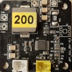
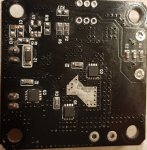
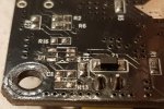
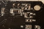
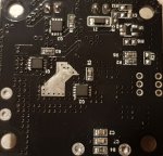
you can see the photo of the board here
20200107_050407.jpeg20200107_050453.jpg20200107_050506.jpg20200107_050906.jpg20200107_050917.jpg
on my board i cant find U1, R13, ( r13 hase damage)
I connected the power to the board, I found that I have a 7.5 volt output.
When connecting the load in the form of a diode video lamp that is powered by 12 volts and consumes 2.5 amperes, the driver gave out 7.3 volts and 1.4 amperes.
I understand that 7 volts is a lot for the laser diode that I will use with this NUBM 08.
I am new in lrhis and trye to beald laser engrave.
help me figure it out okay for my purposes or put me through the garbage that I have to keep away from!
I did not do any mounting and soldering on the driver except soldering 2 wires for the laser diode!
Thanks in advance for any help!
 
Last edited:
HI all!!
bought a driver from techhood on ebay.
now i can't post any link, and creat this QR code, this is the link to eBay
View attachment 67534

you can see the photo of the board here
View attachment 67529View attachment 67530View attachment 67531View attachment 67532View attachment 67533
on my board i cant find U1, R13, ( r13 hase damage)
I connected the power to the board, I found that I have a 7.5 volt output.
When connecting the load in the form of a diode video lamp that is powered by 12 volts and consumes 2.5 amperes, the driver gave out 7.3 volts and 1.4 amperes.
I understand that 7 volts is a lot for the laser diode that I will use with this NUBM 08.
I am new in lrhis and trye to beald laser engrave.
help me figure it out okay for my purposes or put me through the garbage that I have to keep away from!
I did not do any mounting and soldering on the driver except soldering 2 wires for the laser diode!
Thanks in advance for any help!
Hey djidai,

I see this post is from a while ago, so I'm not sure if you already solved your issue or are still looking for help, if you still have questions I can try to help!

I've been thinking about making a new post to share basics of driver design and demystifying some things, but I want to take the time to make a really polished post for that - if you still want info about this driver, I can give some explanations that are particular to this case.

I keep editing this post because although I do want to wait and see if you still want help, I also find it really hard to keep my mouth shut for any length of time. So I'll feel better if I can dispense one piece of advice unsolicited, and wait to see about the rest:

I don't know if you've already figured this out, but you mentioned R13 looking damaged. If you look around R13, you'll notice that C1, R16 and U1 all have no components on them, but do have solder points. It seems unlikely that damage would result in this appearance, so it's likely that the components were never there to begin with. Whoever made this board might have multiple models available, some of which have other features that use those components. If I had to guess, I'd say it was cheaper/easier to just use the same solder layout and just tell the manufacturer not to add the unnecessary parts for this model. In short, I don't think R13 is damaged, I think it was never there to begin with.
 
Last edited:


Back
Top