Welcome to Laser Pointer Forums - discuss green laser pointers, blue laser pointers, and all types of lasers

LPF Donation via Stripe | LPF Donation - Other Methods

Links below open in new window

ArcticMyst Security by Avery

Driver, Diode, Voltage and Test Load Question

Joined
Aug 1, 2016
Messages
4
Points
3
Hey all! I'm getting ready to do my first build using a PL520 module from DTR and a C6 host from Gary at SL. I ordered the host with a 220mA driver. I ordered two Nitecore RCR123A batteries to make sure I have enough voltage to operate the driver. (4.2 to 8.4 volts.) At this point I think I'm OK. I also ordered a test load because I want to understand how to use it and test it with the driver from SL. (I know it's a fixed driver, in this case it's just a learning exercise.) I understand that I need to adjust the test load to imitate the voltage drop of the laser diode, which according to the datasheet is Vf=7V.

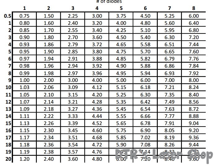
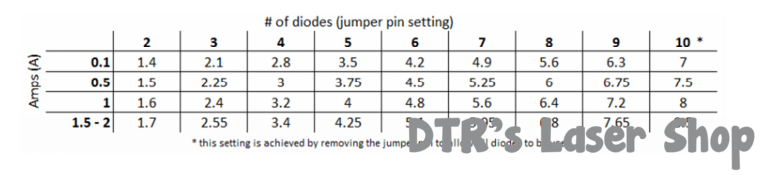
What's melting my brain is what jumper setting do I use to test a 220mA driver for a diode with a 7 volt operating voltage? Do the jumper settings represent the voltage? Meaning, I'd set the jumper to 7?

Gary was kind enough to answer my questions so I'm confident that I can proceed with the build and be OK, I'm just trying to understand how to use the test load.

Bonus question: What's the relationship between my source voltage (2 RCR123A = 7.4V), driver voltage requirements (4.2 to 8.4) and diode operating voltage (7V)? Does my source voltage need to match the diode voltage regardless of the driver voltage requirements? Could I feed the driver 5.5V and still drive the diode? (Less than the diode Vf but still within the driver range of input V?)

Thanks in advance for the help, it's much appreciated!

~Mark


DTR

0
Joined
Jun 24, 2010
Messages
5,684
Points
113
Ok so if you got this driver.
DIY 220mA Driver & Pill Module
You would need to use two li-ions in series to power. If you used less voltage like 5.5V it would not light up the diode or very faintly but would not hurt it. It is a buck driver which may work but not the best option as you noted the forward voltage of the diode is 7V. Not sure the dropout on the driver but if it is very good at 0.5V that would mean you need a minimum of 7.5V from the batteries to power the diode giving 0.9V drop from the batteries 8.4V fully charged state before it will start dropping output current. That is using only about half the capacity Li-ions. If it is a 1V dropout that would only give 0.4V and if it is a 1.5V dropout then it will even with fully charged batteries be less than full power from the start.

This is one reason these high forward green diodes really need a boost or a buck/boost type driver.

For testing 220mA @ 7V refer to the plot provided as the voltage drop will vary based on current. If you got the large 20A test load does not look like it will go that low. For the smaller one looks like if you remove the jumper that would get you in setting 10 which should get you what you want for the drop.

 
Last edited:
Joined
Mar 25, 2016
Messages
475
Points
0
Okay so let me get this straight. If I am testing a driver ran at 4.5 Amps and 4.7 Volts, then I should wire up 6 x 1N4001 diodes in series with a 1 Ohm 20 Watt resistor and measure the voltage drop across the resistor in mV?
 

DTR

0
Joined
Jun 24, 2010
Messages
5,684
Points
113
Just to be clear the driver does not regulate voltage but assume you mean the load(diode) you will be using is rated to drop around 4.7V and you want to set the driver @ 4.5A right?

If you are making your own test load you would want to test it to see what kind of drop you are getting with 4.5A with different numbers of diodes to find the amount that matches. Also if the diodes are not heatsinked the the voltage drop can fluctuate quickly due to heat and with 4.5A that could be very quickly. To test your load if you have a bench power supply you can just hook the load directly to it and turn the voltage all the way up and the current all the way down. Turn it on and turn the current up to 4.5A noting the voltage being displayed. That will be your drop at that specific setting. You can also do this with premade loads and suggest doing so even if it did have a nice plot graph as small variations from unit to unit can give fairly big differences.:beer:
 
Joined
Mar 25, 2016
Messages
475
Points
0
Just to be clear the driver does not regulate voltage but assume you mean the load(diode) you will be using is rated to drop around 4.7V and you want to set the driver @ 4.5A right?

If you are making your own test load you would want to test it to see what kind of drop you are getting with 4.5A with different numbers of diodes to find the amount that matches. Also if the diodes are not heatsinked the the voltage drop can fluctuate quickly due to heat and with 4.5A that could be very quickly. To test your load if you have a bench power supply you can just hook the load directly to it and turn the voltage all the way up and the current all the way down. Turn it on and turn the current up to 4.5A noting the voltage being displayed. That will be your drop at that specific setting. You can also do this with premade loads and suggest doing so even if it did have a nice plot graph as small variations from unit to unit can give fairly big differences.:beer:

So if I'm using two feilong 32650s in series through the 4.5 amp sxd driver to power my nubm44 should I make a voltage regulator as well?
 

DTR

0
Joined
Jun 24, 2010
Messages
5,684
Points
113
Nope. Input voltage for the SXD driving a NUBM44 is 7-12V so you are good.:)
 
Joined
Aug 1, 2016
Messages
4
Points
3
Jordan, thanks for the help. I'm sorry it took so long to reply, it's been a busy week.

1) Test Load
I bought the 3A test load. I think I get it now. My 220mA driver is 'between' the .1 and .5 lines, so for a Vf of 7V I'd use setting 10 (no jumper.)

For a mythical 1.2A driver with a diode Vf of 5V I'd use jumper 6, the closest intersection of values. Correct?

2) Drivers
This one is still tripping me up. The setup I described may work with the batteries fully charged (8.2V) and assuming the voltage drop across the driver isn't too great. My 'run time' will be limited by how long the batteries can keep (source voltage - driver voltage drop) > load Vf. Correct?

I was thinking that as long as voltage input to the constant current driver was in range and the driver current wasn't above the max of the diode I was in good shape.

I understand that boost drivers increase voltage so that you can use a single cell. In the case of the PL520, the datasheet says the max voltage is 8V. If I understand correctly, I wouldn't want much of a boost at all for fear of going over 8V. Or am I missing something fundamental? I see a lot of boost drivers that don't list what they boost the voltage to. Isn't that critical info to make sure you stay at Vf?

I also bought a S06J from you and I'm trying to find the Vf for it. All my searches bring this up:

Vf------mA----mW
4.01----50-----38
4.35----75-----81
4.62----100---121
4.88----125---166
5.08----150---209
5.27----175---255
5.41----200---296
5.53----225---337
5.64----250---381
5.73----275---418
5.81----300---462
5.88----325---503
5.93----350---537
5.99----375---579
6.04----400---617
6.08----425---656
6.11----450---692
6.15----475---728
6.18----500---767

I know that the current should stay at or below 450mA. Is the chart telling me that my (source voltage - driver voltage drop) for a 450mA driver can't be above 6.11V?

Thanks for the help, I do appreciate it!

~Mark


Top