

Trinity
0
- Joined
- Apr 23, 2009
- Messages
- 9
- Points
- 0
Hello Guys,
I don't really know if I should start a new topic but its my first time posting so..forgive my ignorance
Here is my situation. [Stumbled uppon a "how to make a burning laser" video] + [remembered my old broken LG DVD recorder] = Laser Fever
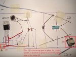
I got the LD from the DVD, found the prints of the driver from a design by ROG8811 and other similar ones from the forums.
Attached is my driver circuit setup. I know its a bit sloppy, but i just wanted to test it first.
Have i done something wrong?...apparently I did since I burnt my diode... :'(
I used a 9 volt battery to power the driver. But as soon i connected everything and pushed the button, the diode flashed brightly for a moment and then it was reduced to a very weak beam spot. Uppon focusing the beam, all i got was a shape similar to this : _._
Can anyone see if I have connected something wrong? The potensiometer maybe..or could it be the 9 volt battery, although i was under the impression that the regulator chip would lower the input voltage to a lower constant output.
Any advice is appreciated")
The first LD is pushing the daises from 6 feet under
I hope I 'll have better luck with the second one(as soon as I manage to find one)
Thank you
I don't really know if I should start a new topic but its my first time posting so..forgive my ignorance
Here is my situation. [Stumbled uppon a "how to make a burning laser" video] + [remembered my old broken LG DVD recorder] = Laser Fever
I got the LD from the DVD, found the prints of the driver from a design by ROG8811 and other similar ones from the forums.
Attached is my driver circuit setup. I know its a bit sloppy, but i just wanted to test it first.
Have i done something wrong?...apparently I did since I burnt my diode... :'(
I used a 9 volt battery to power the driver. But as soon i connected everything and pushed the button, the diode flashed brightly for a moment and then it was reduced to a very weak beam spot. Uppon focusing the beam, all i got was a shape similar to this : _._
Can anyone see if I have connected something wrong? The potensiometer maybe..or could it be the 9 volt battery, although i was under the impression that the regulator chip would lower the input voltage to a lower constant output.
Any advice is appreciated
The first LD is pushing the daises from 6 feet under
I hope I 'll have better luck with the second one(as soon as I manage to find one)
Thank you


")

