Welcome to Laser Pointer Forums - discuss green laser pointers, blue laser pointers, and all types of lasers

Buy Site Supporter Role (remove some ads) | LPF Donations

Links below open in new window

FrozenGate by Avery

DIY Homemade laser diode driver

Status
Not open for further replies.
Daedal said:
I highly doubt it...


GL;
DDL

Oh well, not a big deal. What's important is that the circuit works and seems to do its job well. I am considering modifying my lower powered red with the same circuit. Right now, it just has a dropping resistor.

BTW, the total resistance I did calculate after I changed resistances until the current was where I wanted it. Comes out to only about 5.8 ohms for ~165 mA.

Thanks again,
Jon


[ftp]http://www.radioshack.com/product/index.jsp?parentPage=search&pg=1&summary=summary&cp=&accessories=accessories&productId=2062307&kw=potentiometer&techSpecs=techSpecs&currentTab=summary&custRatings=custRatings&features=features&sr=1&retainProdsInSession=1&y=3&origkw=Potentiometer&x=15&support=support&numProdsPerPage=100&tab=summary[/ftp] would this work for a pot?
 
Good point Xenodius. I should change out my guide to include the new pot. :)

This is good stuff. Glad to see you all working on this. :D

--DDL
 
The source by circuit city took over radio shack rihgt. well here in canada by my town the source doesnt have any i mean any of the parts doesnt have a part not even resistors. its just a small one though. so could you advise any other stores.
 
I picked up the Radio Shack rheostat when I was there recently. It is indeed low resistance, but I didn't use it as it's somewhat large physically, IMO.

There are multi-turn lower resistance pots from Digikey/ Mouser, etc but they aren't cheap. If you stick with single turn, they're much cheaper.

The next time I make this circuit, if I want to get a closer current value, I'll just use one or more 0.5 or 1.0 ohm carbon resistors. There weren't any this low in the RS assortment nor in the store, but Digikey has several 1.0 ohm for pennies.

Jon
 
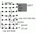
i came up with a way of mounting this on a solder prototype board, cut down.
you may be able to do it with one less trace, if you can mount the pot over the adj lead of the chip. You could almost certainly use one or two less trace holes by being neater. they come in surface mount packages (the LM317) so this could be as small as 40mm x 15mm x 5-10mm. Very good for mounting in tiny cases, like professionally built ones.
 

Attachments

  • ld_driver_diag_001.GIF
    ld_driver_diag_001.GIF
    3 KB · Views: 750
do you know how to connect a simple dvd diode laser? i saw a vid on youtube where a pot was used in a very simple circuit but the guy did not expliant wheather it was in series or parralell with the diode. im guessing series but i want to make sure and i would guess that the pot value would be that of the power supply. i would appreshiate any help offered thanks.
 
I bet that was my video, I tried making it as simple as possible so people follow my tutorial instead of ones that tell you to hook the diode right up to 2 AA's. I am horrible with electronics but I can tell you there are much better tutorials here like this one or the Laser torch.
 
justin889 said:
do you know how to connect a simple dvd diode laser? i saw a vid on youtube where a pot was used in a very simple circuit but the guy did not expliant wheather it was in series or parralell with the diode. im guessing series but i want to make sure and i would guess that the pot value would be that of the power supply. i would appreshiate any help offered thanks.


There is a simple way as I've done one laser that way myself, and that is to use a dropping resistor between the batteries and laser. Others could explain how to obtain the correct value as I can't post links yet, but that is the easiest next to having no resistor at all.

Some recent info I've come across suggests a protective scheme that takes almost any voltage and current surges into account. Two of the components are similar to what Daedal uses in his circuit- the capacitor and diode across the laser diode, except use a 10-22 uF SMT tantalum, 10 V and a MURS20 fast diode. Also to add, in parallel, to the existing parts a 0.1 uF low ESR ceramic SMT capacitor and finally a 0.22- 1.0 F "memory" capacitor, which will force a slower start-up. I recently added these 4 components to a simple resistor dropping circuit and the results have been good so far. I especially like the slower start up. The only drawback is that low ESR ceramics are most commonly available is SMT only (surface mount), which can make soldering a bit more difficult. The same goes for the tantalum, but for tight spaces where you couldn't normally fit a regulator 317 for example, and still want to fully protect the laser diode, this alternative circuit might do the job. Also, if you ever have to unhook or remove the laser diode for any reason, make sure and follow what Daedal says about discharging as these caps, especially the memory cap, can hold a lot of charge for long periods of time.

This 4 part circuit was recommended to me when using a simple dropping resistor. Just why it works, I'm not certain, but my guess is that the caps help level/ stop voltage surges and the extra diode in anti-parallel stops current surges(?).

HTH,
Jon
 
styropyro said:
I bet that was my video, I tried making it as simple as possible so people follow my tutorial instead of ones that tell you to hook the diode right up to 2 AA's. I am horrible with electronics but I can tell you there are much better tutorials here like this one or the Laser torch.

Hey Styro,
I love that video, and the plug you put in for this forum and the GB diodes. Nice goin.. :)
 
Hi,

I'm new to this forum and after reading this thread and other pages about laser diode drivers, have a question that is puzzling me. Does the GB diode not have a built in photodiode or are you guys just not using the PD in your driver design? I am asking this because almost all the schematics of commercial laser drivers seem to incoporate the PD feedback somehow. Does this mean that those driver designs will not work for the GB diode so we can't just pluck a driver off the shelf with specifications matching the GB diode?

I also read that higher power lasers such as green dpss drivers do not depend need to depend on PD output unlike low power drivers so perhaps this also applies to this particular ~200mW red diode as well. Is this the case or am I missing something?
 
Gazoo said:
[quote author=styropyro link=1185701612/105#105 date=1187193481]I bet that was my video, I tried making it as simple as possible so people follow my tutorial instead of ones that tell you to hook the diode right up to 2 AA's. I am horrible with electronics but I can tell you there are much better tutorials here like this one or the Laser torch.

Hey Styro,
I love that video, and the plug you put in for this forum and the GB diodes. Nice goin.. :)[/quote]
The more members here the better! And I wanted the Group buy to go faster so I would get my other diodes quicker lol.
 
Good thinking Styro...LOL. Your video is an awesome advertisement...ha..ha. The diodes sold very quickly towards the end.
 
zerafiel said:
Hi,
I'm new to this forum and after reading this thread and other pages about laser diode drivers,  have a question that is puzzling me. Does the GB diode not have a built in photodiode or are you guys just not using the PD in your driver design? I am asking this because almost all the schematics of commercial laser drivers seem to incoporate the PD feedback somehow. Does this mean that those driver designs will not work for the GB diode so we can't just pluck a driver off the shelf with specifications matching the GB diode?

zerafiel, you are correct in your observation. The driver in this thread is a basic current source that supplies the LD. I believe the circuit is intended to quickly get people started driving their LDs from the group buy.

For commercial drivers, you just have to ensure that you get the correct driver for the LD/PD/case polarity.

Paul
 
Status
Not open for further replies.


Back
Top