millirad
0
- Joined
- Apr 28, 2009
- Messages
- 2,416
- Points
- 63
I just harvested a flyback transformer from an RCA television. It is a DC transformer, rated for 26.9KV. Not sure about which circuit I'll use to create the nitrogen laser yet.


Follow along with the video below to see how to install our site as a web app on your home screen.
Note: This feature may not be available in some browsers.


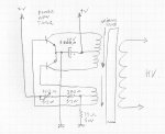
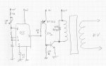
The oscillator circuit will need to be built which will drive the DC-DC LOPT/flyback transformer. I have read that the repetition rate on the laser firing must not be higher than 100HZ, and the flyback transformer does not like to be operated at less than ~15KHZ. So what is the solution? ;-/
 ), but keep the current around 1 ampere or few more (if you see like 3 or 4 ampere, isn't the right coil) ..... when you have found the correct one, you can solder directly the wires to the flyback transformer
 BTW, I appreciate your help +1 rep.
")
^ No, the 15 KHz thing (15625 Hz, to be precise), is just the frequency for which these TV flyback transformers are optimized ..... then you just feed the assembly with the DC current that come out from it, and the resonance of the assembly and spark gap decides the frequency at what the cavity works.
That assembly use the transformer just for power up the system, not for set up the frequency, you're right.
 )
) )
)