Welcome to Laser Pointer Forums - discuss green laser pointers, blue laser pointers, and all types of lasers

LPF Donation via Stripe | LPF Donation - Other Methods

Links below open in new window

ArcticMyst Security by Avery

Disabling/bypassing driver switch

gozert

0
Joined
Nov 18, 2014
Messages
1,076
Points
63
Hey guys. I recently bought two 532nm modules from Offroadfreak that are meant to be used in pen pointers. However, I want to use one of them in a host that has a tailcap clicky switch. How can I disable, or better said bypass the switch that's on the module so it turns on instantly when connected to a battery?

Here a picture of the modules (hope you don't mind me using your pic Offroadfreak)
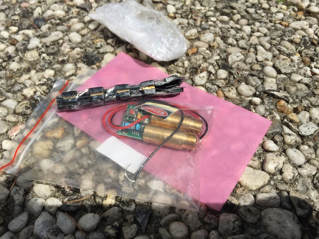
A69B315A-BE2D-4460-A765-4CDACCB80269_zpsuhxlcgql.jpg


gozert

0
Joined
Nov 18, 2014
Messages
1,076
Points
63
Last edited:

BowtieGuy

0
LPF Site Supporter
Joined
Oct 14, 2012
Messages
6,090
Points
113
Check out post #7 in that thread, if their are four contacts, you can determine which two need to be bridged that way.
 
Last edited:

gozert

0
Joined
Nov 18, 2014
Messages
1,076
Points
63
You're right. A moment after I posted I saw it. Too late to edit though haha. About the module being case positive, in this case I just connect the positive wire to the host and the negative to the battery right? Or is there a whole different method for getting it working when a module is case positive?

Edit: nevermind I think I got it. Thanks again!
 
Last edited:

BowtieGuy

0
LPF Site Supporter
Joined
Oct 14, 2012
Messages
6,090
Points
113
Yep, you can just put the battery in with the (+) facing the tailcap, as long as you have a good electrical connection between the module, and the host.
 

gozert

0
Joined
Nov 18, 2014
Messages
1,076
Points
63
Starting the build in an hour or so, but wanted to confirm some things before messing up a module.

7mHntUu.png


So I took this pic from another thread and added a bit. Do I need to isolate the whole module from the host, or can I just fit the positive wire between the host and module without any isolation?
 

BowtieGuy

0
LPF Site Supporter
Joined
Oct 14, 2012
Messages
6,090
Points
113
You don't want to isolate the module from the host, you need an electrical connection from the body of the module to the host (+). You shouldn't need the pos. wire at all.
I see you are showing a flexdrive driver in your diagram. Those 532nm modules have the driver already built in to them.
 
Last edited:
Joined
May 14, 2013
Messages
3,438
Points
0
Hey guys. I recently bought two 532nm modules from Offroadfreak that are meant to be used in pen pointers. However, I want to use one of them in a host that has a tailcap clicky switch.

You didn't say what host you are using, with some hosts the heat sink and module will be isolated from the host because of anodizing. You should test it with your DMM to be sure because there is a possibility you may need the + wire but probably not.

Alan
 

gozert

0
Joined
Nov 18, 2014
Messages
1,076
Points
63
You don't want to isolate the module from the host, you need an electrical connection from the body of the module to the host (+). You shouldn't need the pos. wire at all.
I see you are showing a flexdrive driver in your diagram. Those 532nm modules have the driver already built in to them.

The flexdrive already in the picture and I forgot to took it out, sorry for the confusion. The positive wire is on the very far end of the driver on the modules side. Not sure what exactly the driver is that this thing is using, but it's already soldered to the module.

Here are pictures of the actual host and module. The module is already sitting in the heatsink.

e5tHTMz.jpg


bjDtS7F.jpg
 

BowtieGuy

0
LPF Site Supporter
Joined
Oct 14, 2012
Messages
6,090
Points
113
Looks good, you may want to add a spring to the (-) contact of the driver for better contact, and to keep from pushing the driver against the diode.

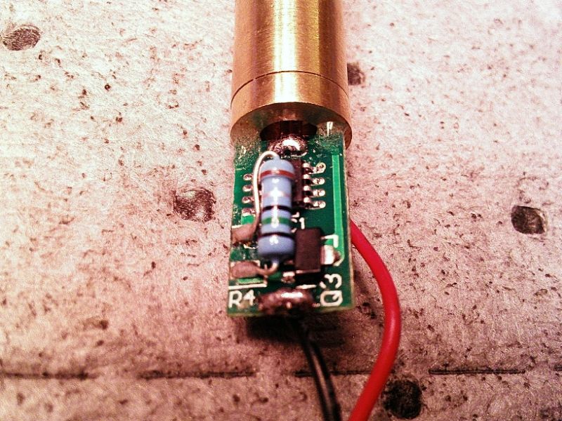
Sometimes I'll add a little dab of epoxy to the driver board (see picture below) where it meets the diode, this will also help to keep the driver from being forced against the diode.


3736b510-62ca-427a-8d34-73305f1400e0_zps662b41ec.jpg
 
Last edited:

gozert

0
Joined
Nov 18, 2014
Messages
1,076
Points
63
Looks good, you may want to add a spring to the (-) contact of the driver for better contact, and to keep from pushing the driver against the diode.

Sometimes I'll add a little dab of epoxy to the driver board where it meets the diode, this will also help to keep the driver from being forced against the diode.

Yeah I was planning to do that. Otherwise it's gonna be difficult having a good connection with the battery. Just to be clear, can I cut off the positive wire and let the module touch the host?
 

BowtieGuy

0
LPF Site Supporter
Joined
Oct 14, 2012
Messages
6,090
Points
113
Yes, assuming, as pi has mentioned, that there is no anodizing, and you have a good electrical connection from the module to the host.

Edit - If you add a spring to the driver, check for your available length in the battery tube, you may have to use a shorter battery.
 
Last edited:

gozert

0
Joined
Nov 18, 2014
Messages
1,076
Points
63
Yes, assuming, as pi has mentioned, that there is no anodizing, and you have a good electrical connection from the module to the host.

Edit - If you add a spring to the driver, check for your available length in the battery tube.

Got it. Thanks for the help both of you!


Top