- Joined
- Feb 18, 2013
- Messages
- 744
- Points
- 28
Ok, I grabbed THIS at my local home depot a few weeks ago. A two pack for nine bucks, hoping they might make decent host. After dissasembly, it wasn't promising.
Then i got three fasttech modules. I was wanting to put them in something simple, mainly to use it easily. Then i happened to think of these flashlights.
So I took one of the modules and slid it into a black anodized aluminum heatsink. Then I opened the flashlight back up and removed the large plastic retainer that held the LEDs and driver board. I removed the guts from the retainer, and slid the module in. The heatsink stopped the module just right for the button to line up.
Over the last few days, as a little side project, i got this working. I put a gob of tape in the back of the plastic insert to help support driver/module. I used more tape to get a snug fit for the HS. While doing this, the neg wire came off, which was fine for my plan. I cut the positive just short enough to go through the hole in the retainer, and striped about a 1/4in of insulation. Then i unsoldered the metal contact from the LED board and soldered it to the negative of driver, making this a positive ground.
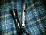
Here is both. The black is still normal, the silver laserfied.

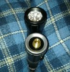
Top shot.

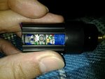
This is the insert after module installed.

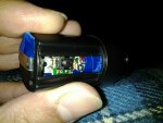
Bottom view of soldered on contact.

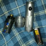
Pre final assembly. The 3xAAA holder is the modified one from my first build. I used two AAA alkaline batteries, but had to put them in upside down.

I taped the positive so it would make contact with host, then slid it in and screwed the top on. It's not perpectly aligned, but it works. :wave:


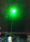
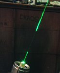
For something that was thrown together, i thing it's pretty nice.
Just thought i'd share. Thanks for looking.
Then i got three fasttech modules. I was wanting to put them in something simple, mainly to use it easily. Then i happened to think of these flashlights.
So I took one of the modules and slid it into a black anodized aluminum heatsink. Then I opened the flashlight back up and removed the large plastic retainer that held the LEDs and driver board. I removed the guts from the retainer, and slid the module in. The heatsink stopped the module just right for the button to line up.
Over the last few days, as a little side project, i got this working. I put a gob of tape in the back of the plastic insert to help support driver/module. I used more tape to get a snug fit for the HS. While doing this, the neg wire came off, which was fine for my plan. I cut the positive just short enough to go through the hole in the retainer, and striped about a 1/4in of insulation. Then i unsoldered the metal contact from the LED board and soldered it to the negative of driver, making this a positive ground.
Here is both. The black is still normal, the silver laserfied.
Top shot.
This is the insert after module installed.
Bottom view of soldered on contact.
Pre final assembly. The 3xAAA holder is the modified one from my first build. I used two AAA alkaline batteries, but had to put them in upside down.
I taped the positive so it would make contact with host, then slid it in and screwed the top on. It's not perpectly aligned, but it works. :wave:
For something that was thrown together, i thing it's pretty nice.
Just thought i'd share. Thanks for looking.
Attachments
-
 defiant.jpg559.6 KB · Views: 811
 -
 defiantFtmod-pt.jpg391.5 KB · Views: 546
 -
 defiant532.jpg421.7 KB · Views: 543
 -
 defiant-lightlaser.jpg395.1 KB · Views: 596
 -
 defiantft-intbot.jpg306.8 KB · Views: 548
 -
 defiantftmod-ins.jpg371.3 KB · Views: 1,018
 -
 defiantbeam.jpg190.5 KB · Views: 535
 -
 defiant-beam.jpg202.6 KB · Views: 668


