Welcome to Laser Pointer Forums - discuss green laser pointers, blue laser pointers, and all types of lasers

LPF Donation via Stripe | LPF Donation - Other Methods

Links below open in new window

ArcticMyst Security by Avery

DC/DC boost converter really simple schematic

Joined
Aug 26, 2007
Messages
334
Points
0
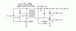
I found this cool schematic online, but I can't tell what the polarity of the capacitors are! Can someone tell me the polarity of the capacitors on the right side of the transformer?
PLEASE! :)

I got this working at 60 volts. And its only 10mA because I skipped the whole right side of the circuit cause I couldn't figure out the capacitor polarity. :(

On the original page(that I can't find now) it said that the capacitor and diode arrangement on the right side increased the power of the circuit.

Can someone type the polarity according to the number of the capacitors?
tell me + or - for each dot


EXAMPLE:

1:+

2:-

like that.


It would be a tremendous help. I'm sure everyone on the forum will be able to use this.
 

Attachments

  • triple.gif
    triple.gif
    3.6 KB · Views: 20,834


Joined
Jul 27, 2007
Messages
3,642
Points
63
looks to me like the second half of the schematic is a voltage doubler, this image should help you out.

img277.gif
 
Joined
Aug 26, 2007
Messages
334
Points
0
MarioMaster said:
looks to me like the second half of the schematic is a voltage doubler, this image should help you out.

img277.gif


That doesn't quite help me.

Does the right side of the circuit alternate?
This is really confusing.
 
Joined
Jul 27, 2007
Messages
3,642
Points
63
ok i get what you're saying, i think you need to get ceramic capacitors or another type that is polarity independent, the way the circuit is set up the capacitors will be receiving charges from both polarities. And yes the second half of the circuit does alternate since you are coming from a transformer. After the diodes however the output will be pulsed DC
 
Joined
Aug 26, 2007
Messages
334
Points
0
MarioMaster said:
ok i get what you're saying, i think you need to get ceramic capacitors or another type that is polarity independent, the way the circuit is set up the capacitors will be receiving charges from both polarities. And yes the second half of the circuit does alternate since you are coming from a transformer. After the diodes however the output will be pulsed DC

I didn't know certain capacitors could be 2 different polaritys.

One more thing to ask. Which of these should I use? and would it matter if http://www.radioshack.com/search/index.jsp?sr=1&origkw=capacitor&kwCatId=&kw=capacitor&pg=1I got a 10 microfarad instead?


Top