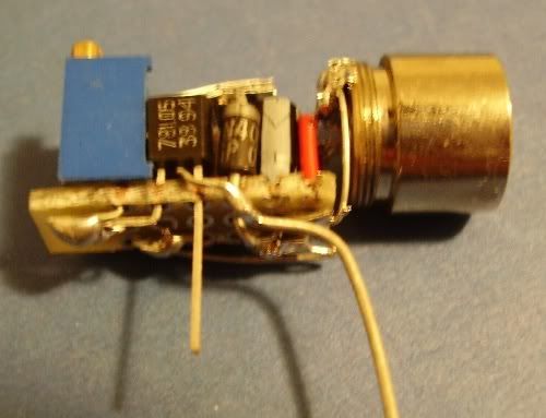
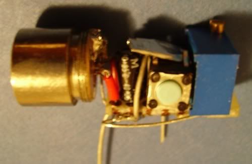
I sort of copied Rog's bluray driver design and here is what I came up with.
Everything crammed into a 20 x 10 x 10mm driver
With a little foil to bypass the switch.
I almost screwed up when my cathode pin broke when I was removing the PCB attached to it

Initially soldered a wire to the diode casing but that kept coming off so I mass soldered the wire to the aixiz housing. Ugly but works.
I have a problem. My DMM ohm meter function is screwed up and I have no idea what the resistance is on my pot and don't dare to adjust it. So basically I have no idea what current is going through my diode. Should have put in a 1ohm sense but mine was too big.
Any ideas how to estimate the resistance of the trim pot without an ohm meter. How do I know when I reach the end of the 25 turns? Will the screw pop out if I screw too much? Does it go inwards when I screw clockwise like normal screws? It doesn't seem to be moving though. I am afraid to go CCW too much either.
A quick check, when I screw clockwise, pin2 goes towards pin 3 according to the spec sheet. So screwing clockwise reduces the resistance(pin1&2 connected) and increases my current?
My voltage values running off a 7.7v weak 9v-battery
Vout= 5.03v
Vdiode=4.54v
Vpot= 0.38v
So I guess it should be alright. Now to fit that in a housing.
Thanks for all the help!


