Welcome to Laser Pointer Forums - discuss green laser pointers, blue laser pointers, and all types of lasers

LPF Donation via Stripe | LPF Donation - Other Methods

Links below open in new window

ArcticMyst Security by Avery

Converting a 532nm 50mw laser pointer to a 200mw 808nm Infrared laser

Joined
Oct 23, 2011
Messages
16
Points
0
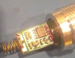
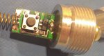
I unscrewed the laser diode assembly to look at it again. Something I didn't expect to see - both of the laser pointers have a momentary contact switch mounted on the diode power supply board. I assume they bridged the switch contacts because the LPs are "on" whenever the circuit is complete - which is what the tail switch does. It just surprised me to see the extra parts - usually any Sino electronics I get are stripped to the barest minimum to make a circuit function.

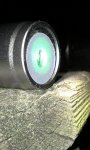
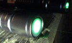
Another thing I noticed while testing... both of the LPs have spacial filters a few mm outside the final lens. I didn't think about this when I got them - I assumed these were cosmetic stickers applied to make it "pretty". While examining the lens assy while illuminated, I noticed the large amount of illumination inside the stickers - then it hit me... this is to drop out some of the frequency artifacts in the beam by just blocking the noise and allowing the main beam through. One of the filters is off-center significantly. I considered removing them both, but I'll wait until I am ready to break the laser assy down. No sense making it harder to look at by introducing noise.


Joined
Sep 20, 2013
Messages
17,253
Points
113
Are you sure what you are looking at is a spatial filter? It would be very unusual to find one inside any pointer, much less a DPSS 532nm laser pointer. I have used spatial filtering in holography and it is difficult and expensive. Whatever is in there, I'm sure it isn't a spatial filter. Normally a spatial filter is made up of an objective lens and a pin hole which is adjustable in three axes.
 
Last edited:
Joined
Jan 29, 2014
Messages
12,031
Points
113
I've seen those switches on 532nm modules too which were wired around or the switch bridged so the tail cap would be the only switch. You are right, an added expense, but they might be buying those modules already made, manufactured that way by someone else so they can work either way as a selling point. If you could link to some photo's I'd like to see the pointer.
 
Joined
Oct 23, 2011
Messages
16
Points
0
Are you sure what you are looking at is a spatial filter?
...
Whatever is in there, I'm sure it isn't a spatial filter. Normally a spatial filter is made up of an objective lens and a pin hole which is adjustable in three axes.

You are correct. I was going from memory and over simplifying. What they have done is include an aperture (a large pinhole) to physically remove some of the splatter/artifacts.

I pulled the vanadate assembly from one the LP with the lower current and non-centered sticker (pinhole). I may try to re-center the sticker, and if I do, I'll get some resultant beam shots with/without the aperture.
 
Joined
Oct 23, 2011
Messages
16
Points
0
...they might be buying those modules already made, manufactured that way by someone else so they can work either way as a selling point. If you could link to some photo's I'd like to see the pointer.

That's a good point. I didn't think about it until just now - with a different barrel to accommodate the "button", and a "locking" tail cap, it is potentially a "protected" LP.

With the exception of the switches, the boards in both of the LPs are extremely close copies to the board you showed in the first post. I have a scad of pictures I took last night. I'll try to go through them and find some in-focus ones and upload them as soon as I can.

I also got some beam shots of the resulting 808nm IR output using a cell phone camera. They're seen through the IR filter in the cell phone but the amount of light being picked up is pretty significant. If I get time, I'll also edit some video I made, pre dissection, to show the IR making it out of the LP.
 

diachi

0
Joined
Feb 22, 2008
Messages
9,700
Points
113
I also got some beam shots of the resulting 808nm IR output using a cell phone camera. They're seen through the IR filter in the cell phone but the amount of light being picked up is pretty significant. If I get time, I'll also edit some video I made, pre dissection, to show the IR making it out of the LP.

Like this? :D

295-ir-beam.jpg
 
Joined
Oct 23, 2011
Messages
16
Points
0
Like this? :D

Sigh. No where near as cool. But I recognize that stance. I have tried to crop mine to mask out the floor at the workstation. Cords, plugs, manuals, notebooks, whiteboards, pens, two area rugs, power buses, empty equipment containers, computer speakers, and my feet. Heh... eventually, I gave up.

I am trying to attach some pictures - some fuzzy, low light, poor artistic quality, obviously the work of a hack - but at least something to see. Now I have to see if I can find, order, and label them. And it's only 2:30... and I have to be up at 6am. :-( I knew lasers could be dangerous...

Well, jokes on me... I'll have to label them vicariously...
If they're in the same order that the message preview shows, there would be:
Pic 1: A closeup of one of the drivers. I tried to get enough contrast so that the components could be easily read... I may have better shots is requeseted.
Pic 2: What the heck is that? That's a beam shot of the silver LP with the final lens unscrewed. I was going to size and evidently thought my feet were a refrence.
Pic 3: Close up of the two... the silver one and the BSL (Big Scary Laser has a label).
Pic 4: Close up of the business end of the lesser LPs... you can see enough of the internal illumination to know that there's a lot of splatter being masked by the sticker. The result? Cleaner beam as the distant end. It also removed some of the energy, but hey, it's purtier.
Pic 5: Same again, with slightly different lighting.
Pic 6: A close up of the naffy little sticker they use for a aperture. I will eventually peel this off and then have some "before" and "after" pictures to see how much ugly it actually hides.
Pic 7: A close up of the other board, flip side. Ditto, tried to make it readable, and ditto, can try to find my better pictures, if they ever make it to dropbox.
Pic 8: I took several pictures of the resulting IR beam. This is with the cell phone camera, which is reasonably modern, and has a build in IR filter. That THIS much be being seen is indicative of a whole lotta light goin' on. This pic is WITHOUT the final lens (and naffy sticker), and I think it gives a neat view of the diode internals. This was taken from 18" high. The resulting beam is about 10'5" long, and 2" wide at the ends, and about 2.5" wide in the middle.

I was concerned about too much energy - too high a density. This is not what I figured. This will most likely have to be used in close proximity, if not in contact, to get the density up.
On contact, the beam measures (approx) 5/8" by 3/16", or by my estimate, 0.75 cmsq. Even if the conversion efficiency was a straight 33% , that would be, at best 1.33W x 33% = 0.44W output from the diode, for 0.58 J/cm^2 *** IF my guestimates are not too outrageous and my math reasonable this late a night... ***

Less than I hoped for, but better than nothing. I can't do better unless I find/build an LPM - which is unlikely any time soon.


-------
Note: I am discounting any inefficiencies contributed from the LD power supply - I have no idea wx it linear or not, what the vdo is, or what the vdiode is. I could probably approximate much better to assume the current is straight in series and use idiode x vdiode for the Pdiode and take 33% of that - but even that's a guess... a much lower.

I am probably doing this wrong - but it's 3am now. Dang it.
 

Attachments

  • 2016-08-03 23.34.04.jpg
    2016-08-03 23.34.04.jpg
    296.6 KB · Views: 126
  • 2016-07-26 15.45.16.jpg
    2016-07-26 15.45.16.jpg
    257.2 KB · Views: 134
  • 2016-07-26 15.48.04.jpg
    2016-07-26 15.48.04.jpg
    233.6 KB · Views: 76
  • 2016-08-03 21.33.40.jpg
    2016-08-03 21.33.40.jpg
    193.2 KB · Views: 113
  • 2016-08-03 21.34.37.jpg
    2016-08-03 21.34.37.jpg
    174.2 KB · Views: 96
  • 2016-07-26 15.41.01.jpg
    2016-07-26 15.41.01.jpg
    362.5 KB · Views: 107
  • 2016-08-03 23.33.30.jpg
    2016-08-03 23.33.30.jpg
    291.9 KB · Views: 153
  • 2016-08-04 00.02.20.jpg
    2016-08-04 00.02.20.jpg
    191.1 KB · Views: 114
Joined
Sep 20, 2013
Messages
17,253
Points
113
If you had a collimating lens close enough to the diode's emitter, and were able to focus it, you would be done. That is, unless I've missed something. :)


Top