Welcome to Laser Pointer Forums - discuss green laser pointers, blue laser pointers, and all types of lasers

LPF Donation via Stripe | LPF Donation - Other Methods

Links below open in new window

ArcticMyst Security by Avery

Can a TMP36 as a LPM Meter Sensor?

Benm

0
Joined
Aug 16, 2007
Messages
7,896
Points
113
I would not worry too much about press fitting them using some heatsinking compound. I've done this many many times with transistors that come in the exact same package and it never posed a serious problem.

Those were pushing a couple of watts out, and here you only need it to make decent contact to get a reference termperature, so less mechanical force (less tight of a hole) is required.

As for how to construct the entire thing... would these sensors be sensitive to ambient visible light, or can you just use them in a normally lit room to measure the temperature of a nearby object?

They seem to be operating much like those contactless IR thermometers just without the optics to focus on anything a bit further away (perhaps they are used in those with some additional optics, not really sure).


AngelG

0
Joined
Nov 6, 2016
Messages
92
Points
0
No, direct visible light should not be a problem, the lens has IR filter.
But If you want to measure something distant in the room, you'd need additional optics, because the field of view of the bare sensor is too wide and you'll get the average temperature which would not be the required temperature.

As for the transistors a loong story comes to my mind. It should have been more than 20 yr ago, because nowadays we have choice among many different packages. During the Cold War, in Bulgaria we had our own semiconductor factory, and my choice (as a little schoolboy) initially was among their products. Their medium-power Si transistors had this package. Later this problem (and our semiconductor, CPU, HDD, CD factories ) disappeared.

However, nowadays, given the rate of the semiconductor companies corporate mergers (for more than 100 billion USD this year) I'm not sure for how long we'll have this great choice. To give an example: The M0 CPU I had in mind was MKL26. I started to work with them 2yr ago just to show to a friend that any ARM can be programmed for free with GNU tools.
It was produced by Freescale, a Motorola spin-off. Last year it (Freescale) was bought by NXP semiconductor (Philips spin-off ?). This year NXP was bought by Qualcomm, USA... Atmel, Linear Technology, Fairchild, Micrel, National semiconductor, Altera to name but a few were bought also...
 
Last edited:

Benm

0
Joined
Aug 16, 2007
Messages
7,896
Points
113
There is a lot of consolidation in the semiconductor industry for sure. This doesn't mean that components will disappear from the market though, as long as the market is still there.

Sensors like this being available as through hole components is quite interesting though. I was browsing around for some temp/pressure sensors and most of those come only in tiny smd packages (which you can still buy on breakout boards on ebay cheaply). I also noticed some IR sensors similar to the one you mentioned available, at comparable prices.

15 years ago i would have expected that simple through hole components would no longer be produced today, apart from things like high power devices that need it for practical purposes.

Production is still going strong though, mostly because of far-eastern low wages where things are still partly assembled by hand. A lot of cheap chinese gadgets still consist of through hole mounted components (including resistors, transistors, leds etc) that are hand soldered.

I think it will eventually disappear as even in china pick and place machines will become cheaper to operate than people, but this could take a long time.

For a sensor like this having it through hole could still make some sense though, as you might want to position it somewhere in a device where it's not close to the main circuit board.
 

AngelG

0
Joined
Nov 6, 2016
Messages
92
Points
0
I could speak on it more, but to return on the topic, have you thought about a cheap, suitable pipe to mount the sensor in ?
Yesterday, I came up with the idea that perhaps a tin can of peanuts could do the job :). It would look funny, but it has a flat bottom, which can easily be drilled through.
 
Last edited:

Benm

0
Joined
Aug 16, 2007
Messages
7,896
Points
113
I've given it a bit of though. Starting out with a pipe could work, another option would be to take two round heatsinks with a central hole and mount those together, one hole covered by the material to heat up and the other to occupy the sensor.

A tube of material could then be fitted to the side with the foil to minimize cooling due to airflow or even convection.

I guess the best construction would look a bit like the thermal sensors by ophir and such - they must have figured out how to get this right as they are essentially measureing the same effect using a different sensor type.

One thing that concerns me a bit is how to calibrate these things without a know power laser. Measuring the thermal gradient along a strip with a heating resistor permanently attached to the back of it would be a reliable way to calibrate. In case of this contactless sensor the heating resistor would be between the heated foil and temperature sensor making this type of measurement inaccurate.

If the laser absorbing foil also absorbs very well in the far infrared it could be possbile to use a non-laser source as a reference, such as an incandescent bulb of known power placed at a known distance with some aperture in between.

I guess figuring out a way to calibrate this system needs more thought, but i think it could certainly work to measure relative laser powers.
 

AngelG

0
Joined
Nov 6, 2016
Messages
92
Points
0
No, with incandescent bulb you'll get very high inaccuracy. Why ? Because it's an omnidirectional source. It shoots energy in all directions and in the whole spectrum - from far infrared (simply heat) to 450nm blue. You will hardly collect more than 30% of the total energy lost in the bulb.
Talking about references, what do you think about this: A chosen LD is sent to a guy w. precise LPM to be calibrated at a given temperature and w (or w/o) given lens.
It must NOT be overdriven, because then it won't be reference anymore. For example, if HL63193MG was used, it wold cover the range from 50 up to 700mW.
 
Last edited:

Benm

0
Joined
Aug 16, 2007
Messages
7,896
Points
113
Well, for a bulb of equal power, equal sensor material and equal distance this would not matter as long as it is reproducible. Then again not all 100W lightbulbs are the same so that could cause a reproducibility problem.

References are always a problem, which is why i ideally think there should be a method of using a resistor to supply the thermal energy for calibration: current and voltage are easy to measure to anyone can do this at home.

The alternative is to look at afforable references that can be distributed. These could be easy and cheap to build, something like a lpc826 diode press fit into a stock aixiz module with stock lens. Someone will have to measure them individually and note, for example, what current is required to produce 100 mW output at some temperature (not that these are -extremely- temperature sensitive, so an ambient temperature might suffice).

It could be feasible, i guess we are looking for absolute accuracy in the order of 5% here, with relative accuracies much better than that so you can see if, for example, swapping out lenses made a big difference in performance even if the absolute power figure is off.
 

AngelG

0
Joined
Nov 6, 2016
Messages
92
Points
0
AFAIK anything built with GaN crystal inside is not so sensitive to the temperature. One 5.6mm SLD3237 for example.. But they're max 200 mW CW w/o overcurrent...
Unlike the 700mW HL63193MG, the inexpensive solution - LPC826 can serve as reference to max 270 mW. The current must be recorded not only at 100mW, but at several steps, at least at 10 mW, 50 mW, 100 mW, 150 mW, 200 mW, 250 mW, because we must be able to catch any non-linearity to compensate for it.
Another cheap diode is Ml101u29-25, but it is even weaker - 150 mW CW / 400 pulsed.
Now, the low power LASER diodes enter into the calibration scene: Let's take a 15 mW LASER diode, for example SLD3132VF/VFI. It is rated to output 15 mW @ 35 mA. Even with 10 % error, this diode will output in the range 14..17 mW. Do you catch the idea ?
Put 2 of them and you'll get almost accurate 30 mW optical power source. Now tune the current of a more powerful diode so it's output to be the same 30 mW. Add again the beams of the 2 diodes for 60 mW; Tune for 60 mW; Add for 90 mw .....

More on the accuracy: A member here (Blord actually) has tested his diode with 2 different commercial LPMs. He got difference of 5mW at 50 mW (10%) here: Sky laser PL520-50, 520nm green

How I think that this can be done with resistor: a small non-oxidized aluminium island is electroplated with copper, then it's covered with tin solder. A tiny SMD 0805 resistor is soldered on one leg to the foil. The second leg should stay in the air. Then a very thin (as hair) copper wire is soldered to the hanging in the air leg of the resistor.
The goal is most of the heat to be transferred to the foil and only a tiny amount to escape via the thin wire. This setup can be safely used for up to 100 deg.Celsius I believe.

@ Attachment 1 - this tin of chocolate sticks can be my windshield in the future :) First, the sticks must be eaten. The green one failed the test - was too fragile and shallow.
 

Attachments

  • 20161202_195014.jpg
    20161202_195014.jpg
    58.5 KB · Views: 74
Last edited:

Benm

0
Joined
Aug 16, 2007
Messages
7,896
Points
113
I agree that installing a small heater resistor would be a good source for calibration. It could be with one side touching, or just glued on with one face touching.

The downside of it is that it will increase thermal mass regardless and make response times slower. With the contactless sensing it would also be in the way of measuring the sensor plate.

One unorthodox solution could be using the sensor plate/foil itself as the heating resistor for calibration. You'd probably need to shove a heck of a lot of current (at very low voltage) through it, but that would give a heat source indentical from laser light absorbed by a black surface.

There may be some hope in reducing the lag though: these I2C temperature sensors can be read rapidly and with good accuracy (far superior to using anything like a diode or ntc through adc). Trend prediction in software could make them a lot faster.

It does depend on the application you need though: I think this will work well for stable laser outputs with a measurement time in the order of 10 seconds, like direct diode lasers. It could prove tricky to get good measurements on fluctuating sources like ill designed 532 nm dpss lasers, but those seem to be on their way out.
 

AngelG

0
Joined
Nov 6, 2016
Messages
92
Points
0
After clarifying most aspects, I changed my mind - I thought that I'll participate but felt like not building it, but now got interested to kick some tires.
I realized that I have most of the necessary components (designated for other projects):
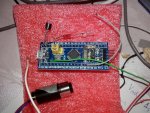
- The "blue pill" board and an unknown "20 mW" LASER are shown @ attachment#1.
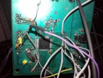
- The attachment#2 shows my custom board with KL26 MCU I mentioned.
KL26 has better ADC, but we're going to use I2C to get the temperature, so I feel like the "blue pill" board is my winning choise, because it's available as a ready-made product.
It has an outdated, but well known STM32 CPU with I2C & USB interface. It has one desired property: a built-in bootloader which allows the compiled firmware image to be flashed via it's serial port using a cheap chinese usb-to-serial convertor with low levels (3.3V preferably). Already tried :) If you build it with Arduino, when I get it working, there will be at least 2 designs. If we succeed, the Chinese boys will copy it & flood the Ebay with clones :crackup:
 

Attachments

  • 20161203_220839.jpg
    20161203_220839.jpg
    119.8 KB · Views: 79
  • 20161203_220917.jpg
    20161203_220917.jpg
    88.4 KB · Views: 78
Last edited:

Benm

0
Joined
Aug 16, 2007
Messages
7,896
Points
113
If i'm building this i'll probably go for the arduino, just because i find it quite easy to program for and work with.

Probably putting an arduino nano v3 with usb interface in there is a nice idea - you get the data logging on your pc sort of 'for free' as the serial interface is already there. Since these things are so cheap ($2.5-ish) i see no reason other than size not to use them.

A big advantage with the arduino designs is that you need no programming hardware at all. Previously i've used the PIC microcontrollers, and hooking up the ICSP stuff using an external programming box was a bit bothersome.

Surely i'd use cheaper/fewer chips when producing these things by the thousands, but for one-off builds the extra one dollar for the arduino board doesnt really make a difference. As it's all I2C the rest really doesnt matter, unless you want to read the laser diode parameters using a builtin ADC's.
 

AngelG

0
Joined
Nov 6, 2016
Messages
92
Points
0
First: Happy New Year !
The things are moving albeit slowly: My sensor arrived today :san:. So the next week I'm going to "reserve" some time to play with it with the MCU I have at home.
I'm sure that arduino would help me to do it quickly, but i'm fan of doing some things myself like USB device I/O on the USB hardware inside the MCU instead of using the FTDI's ready-made solution. How I did it before: - created a non-existing USB device w bulk end-point, then used RAW I/O with it...

I'll try basic measurements with the sensor and will test it's resistance to a cold light source (like white LED).

Next I'll need some electroplating/chemistry knowledge to oxidize the aluminum foil to a mate dark surface.

I'm planing to approach the calibration problem (with some loss of accuracy) by utilizing 2 identical ..hmmm.. light->heat converters - the "calibrating" one with heating resistor and the "working" - without it.

I don't know whether I'll be able to cut them to match each other in terms of heat resistance...
In the end, i'll try "The low power LD" approach I described.
 
Last edited:

Benm

0
Joined
Aug 16, 2007
Messages
7,896
Points
113
Cool, please share what you come up with :)

I've tried to order some I2C temperature sensors from ebay but have had too little time to tinker with them so far.

I think the two-sensor approach will work out nicely though, and could be something people can build to get a decent meter without having a calibration light source.

I wonder how you'll fare with getting the light absorbing coating on the aluminium though. It could be possible using electrochemistry, but an alternative could also be to just cover it with a thin layer of heat resistant paint. Getting and exact thickness of that is probably very hard, but if you use the two sensor approach it's just about getting an equal layer on both pieces, far easier.
 

AngelG

0
Joined
Nov 6, 2016
Messages
92
Points
0
Update:
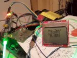
I've succeeded in programming the MCU to work with the sensor so far.
I've hooked a LCD display to print the temperatures onto it.
It's not sensitive to visible light.

But other problems have risen:
The object temperature measured depends on the object's emissivity. (Damn).
This means that it's not good if you want to measure the exact temperature of aluminium foil, because the AL has one of the lowest thermal emissivities:
https://en.wikipedia.org/wiki/Emissivity

My soldering iron at more than 230°C reads 60, because of its shiny metal body.
Edit: I've found a formula: Q = e*s*(T^4)*A*t
where Q = heat (J)
e = emissivity (dimensionless)
s = Stefan-Boltzman constant = 5.67x10⁻⁸ (J s-1m-2K-4)
A = area (m2); t = time (s). So the dependence "temperature vs power" is non-linear.
 

Attachments

  • 20170122_233446_800.jpg
    20170122_233446_800.jpg
    73.8 KB · Views: 82
Last edited:

Benm

0
Joined
Aug 16, 2007
Messages
7,896
Points
113
This is a wellknown problem with bare metals, especially aluminium. It can be overcome quite easily by applying a thing coat of a good emissive material to it. Most paints will do just fine, or you can use radiatior paint that is optically white but black in the IR if you want to.
 

AngelG

0
Joined
Nov 6, 2016
Messages
92
Points
0
Good idea. Now I look for enamel with good thermal emissivity.
The sensor works well against my hands (the human body has high emissivity). Also an enameled pan in my kitchen was measured with realistic result.
It seems that the sensors come from the factory calibrated with a perfect black body object with emissivity close to 1.0.
So we need enamel (paint) with high thermal emissivity to have high resolution of our system. Probably not the paint used to cover the "stealth" aircrafts.


Top