- Joined
- Aug 7, 2016
- Messages
- 138
- Points
- 0


Follow along with the video below to see how to install our site as a web app on your home screen.
Note: This feature may not be available in some browsers.


")
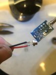
Does the 3rd pin get soldered with the pos or neg?
Depends. What diode are you using?
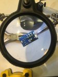
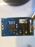
Can we have a picture of the other side of the driver?
HI m,
You got me maybe some one else can chime in Freakin Chinaman..
Rich

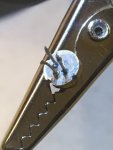
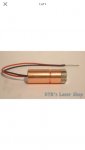
Hope you can see from the Picts. Diode is from DTR 445nm 1.5-2W
Depends. What diode are you using?
Can we have a picture of the other side of the driver?
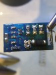
Other side of driver
So what are you using for a module.. it's usually not advised to solder a diode thats not in a module first.. lacks heatsinking.. also if it's a press in module you really can't press it in with leads on it.. if it is a m140 there are plenty of pinout pics on here and I'm pretty sure dtrs website
So what are you using for a module.. it's usually not advised to solder a diode thats not in a module first.. lacks heatsinking.. also if it's a press in module you really can't press it in with leads on it.. if it is a m140 there are plenty of pinout pics on here and I'm pretty sure dtrs website
Christ, soldering on that driver is terrible, cheap Chinese/eBay job?
Does the product listing have any diagrams showing you which pads are which?
Good point on soldering/heatsinking!