Welcome to Laser Pointer Forums - discuss green laser pointers, blue laser pointers, and all types of lasers

LPF Donation via Stripe | LPF Donation - Other Methods

Links below open in new window

ArcticMyst Security by Avery

Boost Driver Adventure 2: Battle

Pixeljoch

New member
Joined
Dec 10, 2020
Messages
4
Points
3
Hey there! So this thread is basically a way for me to document my progress on my boost driver and to share what I currently have, discussions, you know the deal.
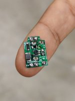
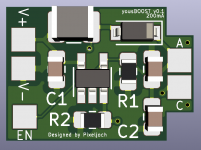
1620427771273.jpgkicad_0754jyr4yg.png
So to get started. The goal is to eventually get a high efficiency 1A boost driver in the smallest possible formfactor I can manage. Current dimensions are 11x16mm, which is not bad, but I've definitely seen smaller. I finally got a working prototype and I tested it on a few different diodes, each with a different operating voltage, all on 200mA. Vin is set on 3.7V, to mimic a Li-Ion battery. On a PL450B, it steps up the voltage to 5.2V, and it draws about 490mA. The efficiency is about 57%, which sucks honestly.
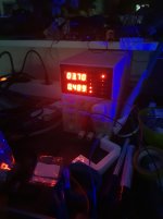
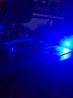
20210510_022839.jpg20210510_022826.jpgDS1Z_QuickPrint3.png

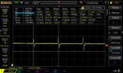
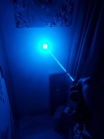
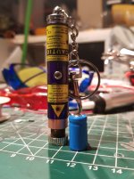
The ripple isn't any better. When settled its about 160mV p-p while I aimed for 50mV p-p. From what I understand currently is that the caps I used apparently decrease in capacity the higher the frequency gets. When it reaches 1.6MHz, the capacity will have dropped more than half. So replacing them with some caps that are meant for switch-mode power supplies, will hopefully solve the problem. I also tested the driver on a 488nm laser diode, which is known to have a very high operating voltage. The driver easily sucks 900mA to boost it to 6.7V at 200mA and the efficiency drops to an appalling 40%. Ripple is practically the same as the PL450B. I did decide to put this diode into a small keychain laser and it worked surprisingly well.
1620427771900.jpg1620427771831.jpg
When it comes to heat, when supplying the PL450B, the driver stayed relatively cool when running for a small while. On the 488nm though, it gets pretty warm after about 30 seconds of continues firing. I'll have to redo the layout and pick the components more carefully next time in order to get the efficiency up and so I don't produce as much waste heat.

That's all for today! So there's definitely still a lot I can improve upon! Exams are coming up though, so I'll have to focus on that for a bit, but I'll still update this thread regularly when developments are made.


Giannis_TDM

Well-known member
Joined
Apr 27, 2019
Messages
895
Points
93
Hey there! So this thread is basically a way for me to document my progress on my boost driver and to share what I currently have, discussions, you know the deal.

View attachment 72652View attachment 72658
So to get started. The goal is to eventually get a high efficiency 1A boost driver in the smallest possible formfactor I can manage. Current dimensions are 11x16mm, which is not bad, but I've definitely seen smaller. I finally got a working prototype and I tested it on a few different diodes, each with a different operating voltage, all on 200mA. Vin is set on 3.7V, to mimic a Li-Ion battery. On a PL450B, it steps up the voltage to 5.2V, and it draws about 490mA. The efficiency is about 57%, which sucks honestly.
View attachment 72653View attachment 72654View attachment 72655

The ripple isn't any better. When settled its about 160mV p-p while I aimed for 50mV p-p. From what I understand currently is that the caps I used apparently decrease in capacity the higher the frequency gets. When it reaches 1.6MHz, the capacity will have dropped more than half. So replacing them with some caps that are meant for switch-mode power supplies, will hopefully solve the problem. I also tested the driver on a 488nm laser diode, which is known to have a very high operating voltage. The driver easily sucks 900mA to boost it to 6.7V at 200mA and the efficiency drops to an appalling 40%. Ripple is practically the same as the PL450B. I did decide to put this diode into a small keychain laser and it worked surprisingly well.
View attachment 72656View attachment 72657
When it comes to heat, when supplying the PL450B, the driver stayed relatively cool when running for a small while. On the 488nm though, it gets pretty warm after about 30 seconds of continues firing. I'll have to redo the layout and pick the components more carefully next time in order to get the efficiency up and so I don't produce as much waste heat.

That's all for today! So there's definitely still a lot I can improve upon! Exams are coming up though, so I'll have to focus on that for a bit, but I'll still update this thread regularly when developments are made.
Yea Hit me up on discord, Don't know why you didn't really, TLDR your component choice, that inductor is way too small to boost to that current and voltage, Hence why you arent getting a proper switching waveform and terrible efficiency. The layout can also be vastly improved.
 
Joined
Dec 8, 2020
Messages
70
Points
8
Hey there! So this thread is basically a way for me to document my progress on my boost driver and to share what I currently have, discussions, you know the deal.

View attachment 72652View attachment 72658
So to get started. The goal is to eventually get a high efficiency 1A boost driver in the smallest possible formfactor I can manage. Current dimensions are 11x16mm, which is not bad, but I've definitely seen smaller. I finally got a working prototype and I tested it on a few different diodes, each with a different operating voltage, all on 200mA. Vin is set on 3.7V, to mimic a Li-Ion battery. On a PL450B, it steps up the voltage to 5.2V, and it draws about 490mA. The efficiency is about 57%, which sucks honestly.

View attachment 72653View attachment 72654View attachment 72655

The ripple isn't any better. When settled its about 160mV p-p while I aimed for 50mV p-p. From what I understand currently is that the caps I used apparently decrease in capacity the higher the frequency gets. When it reaches 1.6MHz, the capacity will have dropped more than half. So replacing them with some caps that are meant for switch-mode power supplies, will hopefully solve the problem. I also tested the driver on a 488nm laser diode, which is known to have a very high operating voltage. The driver easily sucks 900mA to boost it to 6.7V at 200mA and the efficiency drops to an appalling 40%. Ripple is practically the same as the PL450B. I did decide to put this diode into a small keychain laser and it worked surprisingly well.
View attachment 72656View attachment 72657
When it comes to heat, when supplying the PL450B, the driver stayed relatively cool when running for a small while. On the 488nm though, it gets pretty warm after about 30 seconds of continues firing. I'll have to redo the layout and pick the components more carefully next time in order to get the efficiency up and so I don't produce as much waste heat.

That's all for today! So there's definitely still a lot I can improve upon! Exams are coming up though, so I'll have to focus on that for a bit, but I'll still update this thread regularly when developments are made.
Your circuit looks cool! my corcern is related to the warm, 'cause the PL540B losses power efficiency due this factor, an small heat sink and a FAN o the PCB can improve this problem; you need a reverse protection circuit for the PL540B, most of them doesn't have a reverse zener diode integrated, but if yours have it so there's no problem. Can you share the circuit diagram with us? so we can analize the configuration and ways to improve the ripple.
 

Giannis_TDM

Well-known member
Joined
Apr 27, 2019
Messages
895
Points
93
Your circuit looks cool! my corcern is related to the warm, 'cause the PL540B losses power efficiency due this factor, an small heat sink and a FAN o the PCB can improve this problem; you need a reverse protection circuit for the PL540B, most of them doesn't have a reverse zener diode integrated, but if yours have it so there's no problem. Can you share the circuit diagram with us? so we can analize the configuration and ways to improve the ripple.
1rst Of all: I outlined why the ripple was so bad and why the heat problem occurred, A fan Isn't anywhere close to what he should do. That diode on the board isn't for reverse polarity protection.... And I have helped him with all outlined problems and optimized his layout.
 

Giannis_TDM

Well-known member
Joined
Apr 27, 2019
Messages
895
Points
93
Hey there! So this thread is basically a way for me to document my progress on my boost driver and to share what I currently have, discussions, you know the deal.

View attachment 72652View attachment 72658
So to get started. The goal is to eventually get a high efficiency 1A boost driver in the smallest possible formfactor I can manage. Current dimensions are 11x16mm, which is not bad, but I've definitely seen smaller. I finally got a working prototype and I tested it on a few different diodes, each with a different operating voltage, all on 200mA. Vin is set on 3.7V, to mimic a Li-Ion battery. On a PL450B, it steps up the voltage to 5.2V, and it draws about 490mA. The efficiency is about 57%, which sucks honestly.

View attachment 72653View attachment 72654View attachment 72655

The ripple isn't any better. When settled its about 160mV p-p while I aimed for 50mV p-p. From what I understand currently is that the caps I used apparently decrease in capacity the higher the frequency gets. When it reaches 1.6MHz, the capacity will have dropped more than half. So replacing them with some caps that are meant for switch-mode power supplies, will hopefully solve the problem. I also tested the driver on a 488nm laser diode, which is known to have a very high operating voltage. The driver easily sucks 900mA to boost it to 6.7V at 200mA and the efficiency drops to an appalling 40%. Ripple is practically the same as the PL450B. I did decide to put this diode into a small keychain laser and it worked surprisingly well.
View attachment 72656View attachment 72657
When it comes to heat, when supplying the PL450B, the driver stayed relatively cool when running for a small while. On the 488nm though, it gets pretty warm after about 30 seconds of continues firing. I'll have to redo the layout and pick the components more carefully next time in order to get the efficiency up and so I don't produce as much waste heat.

That's all for today! So there's definitely still a lot I can improve upon! Exams are coming up though, so I'll have to focus on that for a bit, but I'll still update this thread regularly when developments are made.
On another note, Your total output capacitance Is more than enough at 44uF for the frequency of the IC. tbh It's excessive and I would recommend changing the caps to 10uF


Top