Welcome to Laser Pointer Forums - discuss green laser pointers, blue laser pointers, and all types of lasers

LPF Donation via Stripe | LPF Donation - Other Methods

Links below open in new window

ArcticMyst Security by Avery

Bench power supply and laser diodes..

Joined
Nov 11, 2014
Messages
60
Points
8
Got two questions..
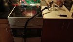
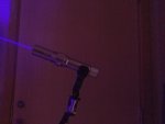
I notice many members seems to run there diode in sinkhousing from bench-power supplies, when benchmarking there diodes.

Is this as straight as it appears.. Are an rookie on this field and not least electronics lab'ish equipment, but judging from the pictures it seems that an adjustable bench-power supply is sufficient as long as you dont floor it with to much current & voltage while adjust it according to LD spec-values with an eye on when it starts to dropped & tip over..

Jumped on a couple of model-unspecified cheap 445nm-diodes a year back from an ebay auction, and these two diodes just been sitting in the draw in lack of dummyload and generel equipment.
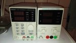
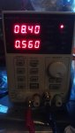
Finally optain a couple of Korad programmable bench-power-supplies there was on sale (KD3005P and KA3003P) and trying to get familiar with the handling and been testing with some plain 1*cent LEDs in numerous colors to sense when they shift/top and role/dropped back...(not that relevant in regards to LDs and the values varies a lot but still give some insigt into the handling of current & voltage for an rookie like me to sense charistica when tilting)

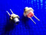
the other question was in regards to these unspecified diodes i ended up with, they where simply labeled 445nm laser diodes with around "1.4A in current-suggestion" in there sealed bags,- was an ebayauction and wondering what LDs-model they actually are' to get an ida of the specification I should run them at..

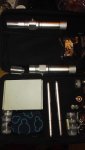
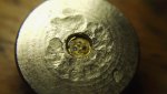
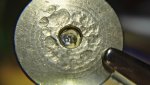
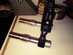
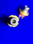
back then when i recived them, I checked the web, and afterwards was of the impression it either was some 5.6mm Osram +1w model or A-140 hence the low price i got them for' and there +/- pin schematic does look a lot like A140 and a short rubber-pin spacer..

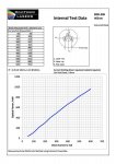
Have checked DTR very informative-site, partically the datsheets on many relevant diodes and a picture walkthrue while testing effect is appreciated from here, but i cant see any detail or test, for A140 but judging from pictures online ' they certainly look a lot like A140.. I would estimate they are A-140 (pic attached bottom)

https://sites.google.com/site/dtrlpf/home/diodes/a140-445nm-diodes

was planning to put the voltage close to 4.8v and the current at 1500ma on the bench and see how much amp it consumes while up'ing the voltage to max 4.8v..

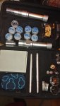
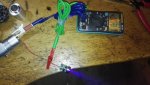
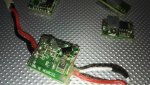
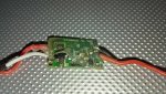
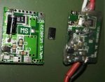
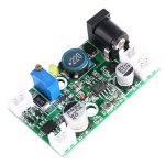
or will it be better to take an 12v TTL 405/445nm driver I allready got in house with adjustable drivercurrent and also adjustable drivervoltage (pic attached) and put that in between LD and bench supply' and adjusted the TTLdriver LD'out-port to 4.8v .. and with an max of 1500mah from the bench-suppl, while having the driver close to the lower current levels and then adjust the current forward from that while having an DMM attached to see what mA it takes from the driver to laserdiode..
 

Attachments

  • IMG_20160205_010735.jpg
    IMG_20160205_010735.jpg
    35.1 KB · Views: 116
  • IMG_20160205_010028.jpg
    IMG_20160205_010028.jpg
    69.1 KB · Views: 258
  • HTB19e6mKVXXXXbZXVXXq6xXFXXX6 (1).jpg
    HTB19e6mKVXXXXbZXVXXq6xXFXXX6 (1).jpg
    91.8 KB · Views: 264
Last edited:


Joined
Oct 25, 2016
Messages
178
Points
28
Those are likely A140s. All credit goes to DTR for this photo but here is an easy way to tell.

P1012168.jpg
 
Last edited:

WizardG

0
LPF Site Supporter
Joined
May 9, 2011
Messages
1,170
Points
113
Correct way to test a laser diode with a benchtop power supply.

1.)with the power supply turned off short out the output of the power supply briefly to ensure no stored charge.
2.)connect the laser diode to be tested (pay attention to correct polarity)
3.)set the current on the supply to zero
4.)set the voltage of the supply to ~2*Vf of the diode
5.)turn on the power supply and slowly turn the current up
 

Benm

0
Joined
Aug 16, 2007
Messages
7,896
Points
113
If it's a good power supply that sould be okay.

To be on the safe side i'd go about it a bit differently though: Turn the power supply on, set both current and voltage limit at zero. Ensure there is zero voltage on the output using a multimeter, then connect the laser diode.

First turn up the current limit to something easily accepted by your laser diode, perhaps 50 mA or so. Next turn up the voltage, up to the point where the supply switches from constant-voltage to constant-current operation (there usually is an idicator for this).

After that you can play around with the current limit. If you ever hit the voltage limit (indicator changes back), lower the current limit, increase the voltage limit and proceed.

This seems a bit elaborate, but for some cheaper power supplies it is the best approach as some have a brief output spike when you flip the mains switch, regardless of what the buttons are set at.

The reasons for it can be a bit complex, but just think of it like the main power source ramping up faster than the voltage to the control circuitry. If you have a scope you can see if your power supplies does this or not. Otherwise, err on the side of caution ;)
 
Joined
Jan 30, 2014
Messages
8
Points
0
Be sure to disconnect the power supply from the diode before flicking the off switch. Lower the current to 0, unplug, then turn off. Or you will end up with spikes from some power supplies.
 
Joined
Nov 11, 2014
Messages
60
Points
8
thx guys for the feedback.
.. the power supply turned off short out the output of the power supply briefly to ensure no stored charge.
yep WzardG I have notice that shorting out the plugs to clean out the hardware / caps. (but still it certainly ring an warning-bell to put that red&black wire together from an rookie-perspective,- have notice the approach to clean out stored charge, and also for generel-review and test some supplys,, but then its "on" with heavy load, and not in regards to cerolized but effecthandling..
Be sure to disconnect the power supply from the diode before flicking the off switch. Lower the current to 0, unplug, then turn off. Or you will end up with spikes from some power supplies.
..Im unsure where it is on possible spike-issues (its new supply, a first for me with an actual adj bench-supply) and not familiar how these liniar Korad are on overcurrent & spikeshandling, - dont got oscilloscope, but judging from the web, the spikes and overshoots should be pretty decent for these liniar PSU from Korad, and not to shabby with the relative-low-price in mind ewen thow relative noise, but it seems to vary on different productionsruns, but will certainly do my best to remember it..(still dont wanne see how my face looked when blowing an expensiv diode from an socalled error 40 in lack of skills.

Those are likely A140s...]
Euphonious, no doubt its the A140 model I reckon, judgíng from the spacers, unless some sellers packed these up, to put on' as safety under shipping, like the case with some general-pinjumpers used as LDpinrack under shipping, but pretty confident to follow the datasheet of the A140 ..//
http://roithner-laser.at/datasheets/ld_div/ld-445-1000mg.pdf
http://cms.diodenring.de/electronic/microcontroller/111-blue-laser-diodes

Next turn up the voltage, up to the point where the supply switches from constant-voltage to constant-current operation (there usually is an idicator for this).

After that you can play around with the current limit. If you ever hit the voltage limit (indicator changes back), lower the current limit, increase the voltage limit and proceed.
Benm, . that its exactly where im at, and have notice this behavior when testing other electronic equpment/loads, and trying to comprihent the meaning of this constant curring-effect that kicks in at some point according to the load on & effect when the voltage kicks in again on actual-values' when it gets to much for the item... (will take a look in the manual so i can get more familiar with the constant-current (CC) variable-features hence when on constant-voltage (CV) levels.)

Anyway its these two cheap peogrammable PSUs (pic attached, weight varies hence transformer max3A vs 5A and so does AC cables thickness) but both of these where quite ttractive prised hence my taxed-personalview here from Denmark' one of them where from Germany (Reichelt) KD3005P 76EU and the other from China KA3005P (66US) both computer-USB & RS232'able and the choice for seperate graphs and valuehandling in each channel-window with sererate channel-load on/off-buttons on computerscreen.. that was something I priotise. (but if I was based in the US, I would likely haved looked at the KA3305 3'channel, at +139US delivered from SRA solder, but that partically-price would more then double when shipped to DK north EU.hence tax & shipping)
 

Attachments

  • IMG_20161223_173454.jpg
    IMG_20161223_173454.jpg
    71.3 KB · Views: 248
  • IMG_20161223_173322.jpg
    IMG_20161223_173322.jpg
    77.3 KB · Views: 121
  • IMG_20161223_173657.jpg
    IMG_20161223_173657.jpg
    69.7 KB · Views: 114
  • IMG_20161223_173903.jpg
    IMG_20161223_173903.jpg
    70.6 KB · Views: 80
Last edited:

Benm

0
Joined
Aug 16, 2007
Messages
7,896
Points
113
These are not the best supplies to drive laser diodes from directly indeed.

Many of these power supplies have current limiting, but it usually is slow. This current limiting is often mostly intended to keep you from damaging the power supply itself, but not to protect the load against excessive output currents at all.

Also you should notice that these power supplies are built to power to power things that don't need current limitation unless you made a soldering mistake or something like that.

Such power supplies are perfectly fine for powering hobby electronic circuits, but are not suitable to power laser diodes directly. They will work fine when simulating a battery on the input of a laser diode driver though.
 
Joined
Jul 10, 2015
Messages
9,799
Points
113
Along with what others have said remember that if you are powering a laser diode and you knock a wire loose, DO NOT reconnect it without turning the voltage and current back down to zero first or you can easily spike and blow your diode.

Also as I use a bench top supply to drive a laser diode I turn up the voltage limit a little bit then the current and back and forth so that both are being limited while in operation, this way if you have an intermittent connection you are less likely to blow your laser diode.
 
Last edited:
Joined
Oct 25, 2016
Messages
178
Points
28
I have the KD3005P and I can tell you for sure it has issues with voltage spiking when mains is switched on/off so careful there! I dont use it much anymore and this is why.
 
Last edited:
Joined
Nov 11, 2014
Messages
60
Points
8
I have the KD3005P and I can tell you for sure it has issues with voltage spiking when mains is switched on/off so careful there! I dont use it much anymore and this is why.

Yes, but as i notice most of the lesser linier PSU in this sub100U(delivered)level got som spiking.

The KA3005P was check by EEV blog, and as i reckon it did decent when it come to spiking.(though' with the pricelevel in mind)

but i have also notice that the majority of the bigger-laser-diode-users in here, seems to work out of extreme budget PSU's (in regards to there YT vids and pictures)
They are ofcourse a lot more competent on the subject then me, but often on the pictures and videos it doesnt look like they have any driver or in-between-item to handle spiking.?
anyway, Im trying to make some diode-exchangeable-cartridge, that i just plug in my battery-housing and suit numerous differen diodes up with appropiate drivers and in sink.(got a bunch of numerous laser-drivers from years ago and now also got amount of diodes) and trying to sense what spec's there actual are in play, and also where these drivers are on there actual-values in regards to there settings.
a dummyload would be ideel, but are little unsure about these pods there are on these drivers.. are there a golden rule, as to what direction there is "gain and decrease on these small cirquit current-pod's" - like clockwise is + and vice versa with anticlockwise or is it variable from driver to driver..

Would it be posssible to just suit these drivers up on the power supply and attach an sinked diode and then turn the PSU up-slowly and then if there is values there jumps out of datasheet-character then adjust the pods or correct diode - and approach it like that' without making seperate dummyload with these dummyload-diodes..
 

Attachments

  • IMG_20170208_190645.jpg
    IMG_20170208_190645.jpg
    97.1 KB · Views: 78
  • IMG_20170208_190250.jpg
    IMG_20170208_190250.jpg
    88.6 KB · Views: 121
  • IMG_20170208_190038.jpg
    IMG_20170208_190038.jpg
    68.1 KB · Views: 115
Last edited:

diachi

0
Joined
Feb 22, 2008
Messages
9,700
Points
113
Yes, but as i notice most of the lesser linier PSU in this sub100U(delivered)level got som spiking.

The KA3005P was check by EEV blog, and as i reckon it did decent when it come to spiking.(though' with the pricelevel in mind)

but i have also notice that the majority of the bigger-laser-diode-users in here, seems to work out of extreme budget PSU's (in regards to there YT vids and pictures)
They are ofcourse a lot more competent on the subject then me, but often on the pictures and videos it doesnt look like they have any driver or in-between-item to handle spiking.?
anyway, Im trying to make some diode-exchangeable-cartridge, that i just plug in my battery-housing and suit numerous differen diodes up with appropiate drivers and in sink.(got a bunch of numerous laser-drivers from years ago and now also got amount of diodes) and trying to sense what spec's there actual are in play, and also where these drivers are on there actual-values in regards to there settings.
a dummyload would be ideel, but are little unsure about these pods there are on these drivers.. are there a golden rule, as to what direction there is "gain and decrease on these small cirquit current-pod's" - like clockwise is + and vice versa with anticlockwise or is it variable from driver to driver..

Would it be posssible to just suit these drivers up on the power supply and attach an sinked diode and then turn the PSU up-slowly and then if there is values there jumps out of datasheet-character then adjust the pods or correct diode - and approach it like that' without making seperate dummyload with these dummyload-diodes..

Just ordered the KA3005D today so I'll post back on how it looks.

Need to get an O-Scope at some point to do a proper test, but will give some views when it arrives.

Ordered a lot of stuff today... Excited! :D
 
Joined
Nov 11, 2014
Messages
60
Points
8
sounds promissing just have in mind the XXXXXXD-model is without computer management (while with an P endmarking they are with RS232 /USB interface and free software) and the KA models doesnt got the joystick(click/turningwheel)interface that are on the KD model that makes the adjustment a joy, but in regards to its the D-model and thereby without the computermanagement with all the bells and whistle as to controlling, then its a huge plus that you got the easy on/off button on the KA-panel with aint the case on KD model, where the on/off load-feature aint as simple..
Have in mind, there is numerous different batches of this model, the KA3003P i got, is very loud fan-noise, while the KD3005P model above is a lot more silent, at least mine, but got the impression that the KDmodel with the insunk bananaplugs, is EU model.
I have attached a couple more bananaplug ports on my KAmodel..(just screw-in, these spadeplugs cost 2 bucks shipped)
54712d1486656600-bench-power-supply-laser-diodes-img_20170209_170705.jpg


I didnt got the budget or reel need for an actual hobby-oscilloscope.. instead jump on a 13US (delivered) oscilloscope and intended as an DIY tool to just leaning the concept.

I gotta admit I am coming short, when it comes to comprihent the world-of-electronics and getting an actual overview...(not something we learn back in school.. :shhh: )

My mind simply cant grasp it' when it comes to the bigger cirquits and values. (laserdrivers, not so much, useally pretty basic, but still my mind dont like electronics)
It comepletely freeze-down in this "digital-mood" tempo.


anyway the 13US oscilloscope is an DIY model that Gearbest had on sell to 19us and something some weeks back and with free points and cashback, the 19us ends around 13US in paid-price, - certainly dont got high hopes for an 13US single channel-oscillioscope, but the DIY-soldering will give some soldering-rutine (ewen thow PCB'chips presoldered) and more importently give me some insigt to basic oscilloscope-concept but how usefull this single channel model can be for an roookie-need like mine, that time will tell..
DSO Shell DSO15001K Digital Oscilloscope DIY Kit-25.40 Online Shopping| GearBest.com
 

Attachments

  • IMG_20170209_170705.jpg
    IMG_20170209_170705.jpg
    56.2 KB · Views: 648
Last edited:
Joined
Nov 11, 2014
Messages
60
Points
8
Damn. all over the place in getting these diodes pressed in a bank-up old brass/copper pill and these 3.8mm BDR209 that looks like dwarfs with these short legs, quite a hazzle with that length.
finally got the hole-pressure-tool to push it true with a bang (not ideel I know), but ewen thow it felled like a extreme tight fit the diode sstill got room for movement, so that casepositive that seem to function doesnt interact, and not able to take connection to hoast thrue the sink..

so soldered a hard pinjumper on positive-driverpad and then will try to attach it to the hoast somewhere down on the inner.(so no smart changeable-cartridge will be in play for this one)

but damn those short legs' its almost impossible to get the legs to connect on the driver-pads when the diode is already quite a bit down in the sink.. annoying these short leg 16x BDR209. (was wondering to use these 16x or wait for the Pl520 50mW 3.8mm in transit for this 3.8mm housing.
anyway with positive taken from the pad on a jumper-wire to hoast, it seem to work, just need to sense where the current gotta be and if I wil try my luck above +600ma.
54709d1486616016-bench-power-supply-laser-diodes-img_20170209_053007.jpg

at this moment its positive that this diode ewen work, was pretty sure that it went tumbled-down in lazingfunction with that hard-press in or with short legs not grasping the pads (extreme short legs) and would need force to take it out and that would ruin it. (so ewen if it break and zoombie out, Im okay, leaned some on this diode//8US)

the slow turning on the PSU did seem to do its job as an "tool" to sense where i was at, ewen thow i was unsure about thermal runaway as to a diode not sinked in optimal and with room to move..(next time, will put a little thermal-paste/grease/thermal-adhesive to make the fitting stick, but was unsure about conductivity thrue this thermal-paste..

btw' "solderpaste" (this grey stuff that first solderflows at some temp and make the soldering in between a diode and housing) would that work, as to when the diode gets warm' if that would make a solderflow around the diode and a better heattransfer, not to mention conductivity, or is that not gonna play, as to not reaching the degrees needed for the solderpaste to flow and manually getting the temp up from the outside, will tumbled the diode?

same with this "silverglue in small tube conductivity" that you use on mylar or flexible pcb when you cant use heat, or when you wanne make seperate traces or reinforce traces.

got all in this in house, but wondering, what would be the best sealent to grease a diode-housing with, as to conductivity and not least thermal-interface with the LDhousing..
 

Attachments

  • IMG_20170209_053007.jpg
    IMG_20170209_053007.jpg
    158.7 KB · Views: 778
  • IMG_20170209_053116.jpg
    IMG_20170209_053116.jpg
    146 KB · Views: 131
  • IMG_20170209_053206.jpg
    IMG_20170209_053206.jpg
    162 KB · Views: 79
Last edited:
Joined
Nov 11, 2014
Messages
60
Points
8
god damn, the +pin breaked off (left one)..
it looks like a fiidle nightmare in trying to get anything to attach to that little restspot on the diode..

assume many users have been in that situation with diodes that have lost one of there pins, any recommendable way in trying to salvage this 209diode..
It does light if i carefull attach the end of an jumperwire on the restspot where the pins where attach (but its so tiny on these 3.8mm)

54721d1486667354-bench-power-supply-laser-diodes-img_20170209_185942.jpg


can i grind the pad and place a soldering that also touches outside of the +pad and tocuhes the diodecasing, just as long as the soldering doesnt touch the -pin, when this seem to be positivecasing-diode and its the +pin that have breaked off.(it seem like it should be doeable on the+pins to also touch outside,while you also get the +pinspot.. will grind it down and put a solderball on the +pin and flow it and hope it binds)

grind down..
54727d1486671450-bench-power-supply-laser-diodes-img_20170209_211339.jpg

54728d1486671450-bench-power-supply-laser-diodes-img_20170209_211354.jpg
 

Attachments

  • IMG_20170209_185942.jpg
    IMG_20170209_185942.jpg
    118.9 KB · Views: 625
  • BDR-209 min600pix resized.jpg
    BDR-209 min600pix resized.jpg
    74.5 KB · Views: 273
  • IMG_20170209_211339.jpg
    IMG_20170209_211339.jpg
    134.2 KB · Views: 603
  • IMG_20170209_211354.jpg
    IMG_20170209_211354.jpg
    138.5 KB · Views: 649
Last edited:
Joined
Nov 11, 2014
Messages
60
Points
8
Hmm, the driver on the PLTB450B-build at relative low current, was not that fund of my thin transperrant heatshrink and the heat from the power simply heated the flowsoldering to a point that the transperant shrinkwrap moved it out of place. (picture)
was running in the ballpark of 1.1 to 1.45amp depending on batteries, but still generated to much heat on driver with the cirquit pieces present..

Will try to move it back and solder it to the (-springpad) and to that pad where there ia still got some solderjunk connected and perhaps put some cobberpads on top of it to manage the heat.

I got a driver that looks identical, but that one got one that looks to be on these DIY load-diodes and was wondering if that part that has flowed off, is equal just in a smaller-smdformfactor, and if it would make sense to exchange that part with another that can optimised this driver for higher current or lesser heat..(a rookie on the elctronic field and the use of different cirquit parts)

The chip' states something down the lines of R17 & R603 (but such a sweated little fellow, not easy to read)

https://static5.arrow.com/pdfs/2012/9/24/1/27/50/138/txn_/manual/slur897.pdf
assume its nr 33 (R17 R603,3.9k Resistor, Chip, 1/10W, 1% std std)

wil try to reflow it back and see if it works, and then save this try & error resistor approach to another occation in the hope in getting some comprihention on resistors and able to manage drivers down that path by tweaking the parts on them in the seek for gains..
 

Attachments

  • IMG_20170224_064310.jpg
    IMG_20170224_064310.jpg
    120.8 KB · Views: 109
  • IMG_20170224_062350.jpg
    IMG_20170224_062350.jpg
    134.3 KB · Views: 96
  • IMG_20170224_064219.jpg
    IMG_20170224_064219.jpg
    205.7 KB · Views: 161
  • IMG_20170224_064404.jpg
    IMG_20170224_064404.jpg
    139.6 KB · Views: 97
  • IMG_20170224_062338.jpg
    IMG_20170224_062338.jpg
    136.6 KB · Views: 111
  • IMG_20170224_101659.jpg
    IMG_20170224_101659.jpg
    159.8 KB · Views: 118
Last edited:
Joined
Nov 11, 2014
Messages
60
Points
8
finally got that S06J x12 diode to play along.

beam shot S06J X12 on left-beam right along BDR209X16 in the right..(plain' no fog or likewise)
Huawei P8max mobilepicture on standard setting X12 & X16
54880d1488243560-bench-power-supply-laser-diodes-img_20170227_232617.jpg

X822 LE2M mobilepicture std sett.. X12 & X16
54887d1488247323-bench-power-supply-laser-diodes-img_20170227_232753.jpg


a stander comming short with close to 1kg of metalhosting dangling..
54881d1488243560-bench-power-supply-laser-diodes-img_20170228_000555-3.jpg


54883d1488244085-bench-power-supply-laser-diodes-img_20170228_001032.jpg


backplate, so i dont blind any neighboors, wicked how much burningeffect there are still in play over many many meters
in infinitybeam clothing on relative low amp 405nm's.
54882d1488244085-bench-power-supply-laser-diodes-img_20170228_001230.jpg


Here an beamshot of Osram PLTB450B with an weak A130 at the side, but the batteries in the 130 was lacking (the osram pltb450b is driven quite konservativ as to an weak driver and the driver that was reflowed do the heat, as to above issue, i encounted where an R603 chip literally flow-away)
Huawei P8Max mobile.
54885d1488245489-bench-power-supply-laser-diodes-img_20170227_233531.jpg

the Osram PLTB450B build
(X822 L2M pic.)
54884d1488245137-bench-power-supply-laser-diodes-img_20170228_014025.jpg

And here two single mode OsramPLT5 450B side by side.
(P8MAX pic)
54886d1488246440-bench-power-supply-laser-diodes-img_20170228_001920.jpg
 

Attachments

  • IMG_20170227_232617.jpg
    IMG_20170227_232617.jpg
    50.1 KB · Views: 701
  • IMG_20170228_000555-3.jpg
    IMG_20170228_000555-3.jpg
    91.1 KB · Views: 698
  • IMG_20170228_001230.jpg
    IMG_20170228_001230.jpg
    109.1 KB · Views: 711
  • IMG_20170228_001032.jpg
    IMG_20170228_001032.jpg
    94.4 KB · Views: 708
  • IMG_20170228_014025.jpg
    IMG_20170228_014025.jpg
    120.7 KB · Views: 733
  • IMG_20170227_233531.jpg
    IMG_20170227_233531.jpg
    64 KB · Views: 781
  • IMG_20170228_001920.jpg
    IMG_20170228_001920.jpg
    34.5 KB · Views: 758
  • IMG_20170227_232753.jpg
    IMG_20170227_232753.jpg
    76.1 KB · Views: 841
Last edited:


Top