Welcome to Laser Pointer Forums - discuss green laser pointers, blue laser pointers, and all types of lasers

Buy Site Supporter Role (remove some ads) | LPF Donations

Links below open in new window

FrozenGate by Avery

Beam splitter/combiner cubes for 14w of 450nm

Hi Alaskan,

It is a good suggestion. In this way I can find use of that NON-polarizing beamsplitter, aliexpress seller sent to me instead of the ordered one. I only need to check if it exactly reflects 50%. And with 3 of those half-mirrors in a row it will be possible to "increase LPM slimit" 8 times!

And since they will reflect excess of light by side and not absorb it, the calculation would be easier than in case of glass filter with unknown opacity, where transparence may change at heating while light is absorbed.

Now I know what NON polarising beamsplitters are useful for!


I have done this.

However this non-polarizing cube beamsplitter seems to not have any ARC (at least visible one). But is lets through 31-33% of the light, what is even better than half in order not to abuse the LPM sensor.

One laser (horozonlal line) originally 7.11-7.12W becomes 2.19-2.24W after this half-mirror.
2nd (vertical line) originally 6.35-6.38W becomes 2.06-2.08W.
So, this percentage maybe a little dependant from polarisation, but not too much.
The combined beam becomes 4.22W, what would mean its original power to be 4.22/0.32= 13.19W.

Interesting, that the 90 degrees reflected beam is only 6.33W. Maybe 2.64W was absorbed/dissipated by the cube?
 
If your cube was dissipating 3W, it would have cracked from the thermal stress.

I would recommend a single piece of glass, rather than complex optics. It's a simple matter of ratios after that. Turn down the laser to a power that you know is readable by your meter. Fire it at a piece of glass oriented at 45 degrees to the beam. Measure also the beam reflected by the piece of glass. You now have a ratio of attenuation, and you have a lower power version of the main beam that is directly proportional to the main beam's power.
 
Hi again,

After couple of weeks I would like to come back with a little update of my "breadboard".

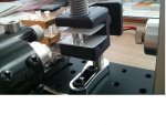
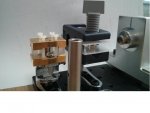
I have added to the PBS (now there is 10mm one from Lasertack) the round waveplate (waverotator) received from OPT (it is 10mm diameter, so can be held in same clamp just before PBS cube) at the entrance of side beam.
After PBS I added a 1D beam expander made of 3x cylindricals pair pressed between 2 brass mounts with 4 nylon bolts in order to avoid glue.

This time it was really difficult to combine 2 horizontal line spots at long range and 2 squares at short range while passing cylindricals, but at end I have a spot which is oval ~1cm long at 2m distance (puts white printer paper in fire in 3sec), and ~2cm long at 5m.

So, like all you said, 3x is not enough, but much better than nothing. I also think that my beam is not strictly collimated, but I just 1D focused it at desired distance.

Since my LPM cannot mesure total output, I mesured the two lasers one by one and have 6.50 + 5.73 = 12.23W.

There can be losses through even AR coated optics, but I am surprised to find out that for good aligning the 2nd laser beam had to enter the waveplate at little angle (NOT perpendicular to waveplate surface). Maybe there is some reflexion because of this?
 

Attachments

  • WP-PBS-3xCyl.jpg
    WP-PBS-3xCyl.jpg
    46.4 KB · Views: 133
  • WP-PBS-3xCyl no 2nd module.jpg
    WP-PBS-3xCyl no 2nd module.jpg
    35.7 KB · Views: 136
Is everything else upstream of the waveplate in line?

When I do cyl pairs I center my focused G2 on a distant point, then center the concave then center and adjust the convex so they all center the same.

You should be able to enter your waveplate straight on, perpendicular that is.
 
Hi Red Cowboy,

Of course not everything is in line. I cannot rotate the position of big clamp vertically - so PBS+ waveplate combination is not 3-axis adjustable.

Maybe I have reflexions because PBS is not horizontal between 2 plastic plates which deformed in the clamp? I will put a metal plate under it later, but do not have it at hand now.

Are there no news from Glutton about GB of 6x?

I have read you are planning to buy whole 8LD blocks or projectors - if you find a good deal, I would like to be in for one, please.

Are NUBM44 also sold as 7LD blocks? I have never seen them in blocks on ebay, maybe I did not search well?
 
Yes, 400 dollars range for whole block would be good.

I agree with tests you do, never seen a pojector inside, but they can have many good things apart of LD blocks: Cooling, knife-edging, LD sockets, high voltage driver which safely drives LDs in series...
However I doubt that those optics inside can give well collimated beam with low divergence. Maybe only concentrate at a close point to burn like styro's lens?

I also thought about Osram 50W chip - there will be 5 LDs in series in each line, so one will not be able to use a separate driver for each LD. The current blocks may also be driven in series from one 32V driver (acc. to tech sheet).

So, I connected 2 NUBM07E (rated 2.3A, max 3.5A in tech sheet) in series and tried to drive them with "microprocessor controlled" DC DC converters from dx (SKU 247601 and 311171) I have bought for my LEDs. They have constant current/voltage functions with preset.

The small downstep converter (B3603, max. 3A) works well from 4x18650 input: I do not see any spark at switching on, it holds preset 2.3A rated current well at ~8.4V (checked with additional volt/ammeter in output circuit).

The big 400W booster (max 10A) was in contrary not so safe: there was blue spark at switching on and even at turned off output it gave almost full 6.2V tension from the LED battery to the LDs (they both slightly glew with 6mA! current).
Maybe all boosters are like that, I do not know.
Then I preset it to 3.5A and pressed OK button to turn on: it reached this current in 4 sec (looks like soft start?), but the additional voltammeter has shown 3.75A (at 8.7V), so also the microcontroller maybe not very precise in this 400W booster.

Now I have ordered B3606 from aliexpress. Want to check out this one.
 
Hi Alaskan,

It maybe a special angle, but the answer can be easier - it is difficult to have PBS in this big clamp stand perfectly straight, so if it is not, then 2nd beam angle of incidence has to compensate some degrees.

The interesting conclusion is that this set can decently work even if not all parts are in line.
 

Attachments

  • Set with PBS not straight.jpg
    Set with PBS not straight.jpg
    75.8 KB · Views: 115
OK, problem solved.

I aligned the PBS with WP, now 2 beams enter it almost perpendicularly.

The total output seems to be a little up: 6.65 + 6.04 = 12.69W.
 
Although the thread is five months old, if you have a beam shot of that 12 watts of output, I'd sure like to see it.
 
Yes beam shot please.

Is your cube a polarizing cube?

It is Right? Already asked I'm sure but just checking, I am going to use 6X cyl correctinn on 2 x nubm44's with G2's and a wave plate on one then a bounce mirror to combine both beams in a cube, the 1mm x 5mm beams should be within the blocks power per area capability and I am sure I am supposed to use a polarizing block even after a 1/2 wave plate but just wanted to be sure that's correct?
Then into a BE for the win.

Thanks.
 
Last edited:
Yes beam shot please.

Is your cube a polarizing cube?

It is Right? Already asked I'm sure but just checking, I am going to use 6X cyl correcting on 2 x nubm44's with G2's and a wave plate on one to combine both in a cube, the 1mm x 5mm beams should be within the blocks power per area capability and I am sure I am supposed to use a polarizing block even after a 1/4 wave plate but just wanted to be sure, also it is a 1/4 WP and not a 1/2 WP that I want, correct?

Thanks.


Needs to be a PBS - regular beam splitter cube would just result in you still having two beams, but at slightly lower powers due to optical losses.

So yes, you are supposed to use a PBS. Yes, 1/2 WP is what you want - it rotates linearly polarized light. A 1/4 WP converts circular to linear and linear to circular.

Two common types of waveplates are the half-wave plate, which shifts the polarization direction of linearly polarized light, and the quarter-wave plate, which converts linearly polarized light into circularly polarized light and vice versa.[1] A quarter wave plate can be used to produce elliptical polarization as well.
 
Last edited:
Can't rep you yet but I owe you 1, Thanks diachi. I assume the wp will be marked for top dead center or is it's clock face position not a factor?

Of course it needs to be set to TDC, Right? Everything else will be height and 3d aligned so the wp will hopefully be marked for its TDC.
 
Last edited:
Hi Guys,

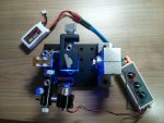
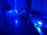
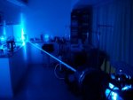
Here I made 2 pictures of the 450nm 12.7W beam from device assembled in March vs. the new 7+W 465-470nm steampunk blaster.
Both at night in the same hotel room. And absorbing the beams by a black carton box (5m away) in order not to blind the handy camera.


Both devices had to be a little realigned because cheap holders do not seem to hold position at transportation.
Also the 1st shot had to be really fast before the hole in the box was burnt through.

1st beam looks tighter because the combined beam from 44s in only 3x expanded, while the combined beam from 07s is expanded about 6-9x (I do not know this ratio exactly but use 3 cylindricals here like Milos suggested in one thread).
 

Attachments

  • 13W at night 24.jpg
    13W at night 24.jpg
    38.5 KB · Views: 62
  • 7W at night 24.jpg
    7W at night 24.jpg
    41.9 KB · Views: 104


Back
Top