brianpe
0
- Joined
- Dec 26, 2012
- Messages
- 56
- Points
- 18
A while ago I built a battery powered lab laser (Battery Powered Labby). It was a fun project but beam quality wasn't that good and I there were some changes I wanted to make to the control electronics.
Meet Labby 2:
Changes from Labby 1:
Thanks all to the great feedback from my first labby - I used a lot of it when designing this laser.
Labby 2 runs for about 3 minutes on full power before it gives a max temperature warning and takes about 2.5 minutes to completely cool back down. It always starts at 0% with the fire switch off when you turn on the key so there are no surprises. It still runs each NUBM44 at 5.5 amps, which is a little more than they want, but I rarely turn it all the way up. It uses a 8000mah RC car LiPo battery (Amazon link here) and can recharge it at four amps, so it doesn't take too long to fill it up when empty. It does not, however, fit in my pocket.
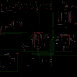
Edit: I was lacking describing the electronics, so here's an update (I've also attached the schematic to the gallery):
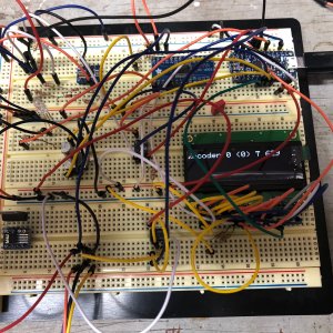
Power to everything is controlled by a 100A mosfet. This way the key switch doesn't have to handle the current to the laser drivers, and also allows me to power up the board when the charger is attached. I'm using an Adafruit Pro Trinket for processing and maxed out all the IO lines on the processor. It knows when the charger is attached, temps to both diodes, PWM control to both diodes, drives the display through I2C and has inputs for the encoder and fire buttons. PWM and power is sent to dual BlackBuck8 drivers preset to a max of 5.5A.
Pressing in on the encoder enables a menu mode where you can choose the display style (%, amperage to diodes or calculated power output) and diode settings (auto - drive one diode till we hit 40% power, then start driving both, each laser independently, both lasers, or run whichever laser has the lowest temp).
I grabbed temperature data off the NTM sensors on the diodes with my last labby but had to actually cut the pins to the processor because it was preventing laser startup. This turns out to be because the processors analog inputs have a 10k impedance, and was causing the BlackBuck to think the lasers were over temp. I now buffer the NTM voltage through op amps.
The display is 3V logic, so I chose a 3V processor. The PWM inputs to the BlackBuck require 5V, however, so there is a level shifter to shift the signal up to 5V. I'm not terribly happy with this. First, when then CPU is resetting the outputs are all high impedance which the level shifter interprets as a "high". Result: Reboot the processor and both lasers turn on. Bad. I worked around this by controlling the enable pin of the 5V regulator by the processor so I don't even enable outputs until I'm ready. But there is also some low voltage noise on the outputs. It's small, and would never be seen as a "1" to logic, but the BlackBucks do see this is an analog signal. The result is that even at 0% power, as long as that 5V regulator is enabled the lasers have a small amount of glow (way below threshold). I didn't notice this till very late -- it's totally invisible when you're wearing goggles. I worked around this in software. I only enable 5V when the laser is firing.
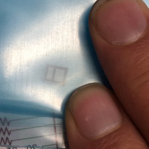
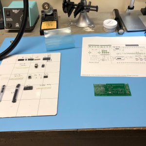
LiPo charging is handled through a Linear 4002 LiPo charging IC. I originally chose a different IC but I bit off more than my newbie SMD skills could handle. Here's the original chip:
The 4002 requires an external mosfet but was a slightly better form factor for me. I added a good copper pour to heat sink the mosfet and used an external heat sink glued to it since my prototype melted its solder joints! So far it has been working fine but it's a constant worry for me. The mosfet does get hot. It's switching at 500Khz.
BEAM SHOT:
Oodles of photos here:
Meet Labby 2:
Changes from Labby 1:
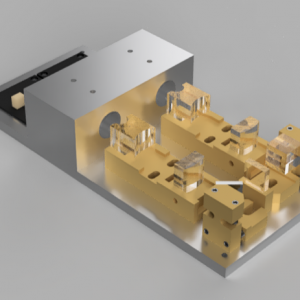
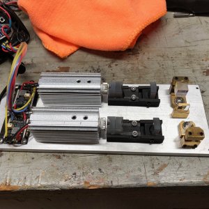
- Extra 2X cylindrical lens mounted back to back with 6X. Hugely improves beam shape.
- Cylindrical lenses mounted on custom 3D printed mounts.
- Larger heat sinks for better run time.
- Much safer electronics. Impossible to turn key switch on and find laser was left 'on'.
- Battery built-in, built in charger.
- Temperature monitoring of diodes, with bar graph on front display.
- Display can show percentage, amps going to diodes, or estimated output power.
- Smarter diode selection, so lower powers only use one diode. Selectable selection modes including a "maximize runtime" mode that runs one diode at a time and chooses the coolest diode every few seconds.
Thanks all to the great feedback from my first labby - I used a lot of it when designing this laser.
Labby 2 runs for about 3 minutes on full power before it gives a max temperature warning and takes about 2.5 minutes to completely cool back down. It always starts at 0% with the fire switch off when you turn on the key so there are no surprises. It still runs each NUBM44 at 5.5 amps, which is a little more than they want, but I rarely turn it all the way up. It uses a 8000mah RC car LiPo battery (Amazon link here) and can recharge it at four amps, so it doesn't take too long to fill it up when empty. It does not, however, fit in my pocket.
Edit: I was lacking describing the electronics, so here's an update (I've also attached the schematic to the gallery):
Power to everything is controlled by a 100A mosfet. This way the key switch doesn't have to handle the current to the laser drivers, and also allows me to power up the board when the charger is attached. I'm using an Adafruit Pro Trinket for processing and maxed out all the IO lines on the processor. It knows when the charger is attached, temps to both diodes, PWM control to both diodes, drives the display through I2C and has inputs for the encoder and fire buttons. PWM and power is sent to dual BlackBuck8 drivers preset to a max of 5.5A.
Pressing in on the encoder enables a menu mode where you can choose the display style (%, amperage to diodes or calculated power output) and diode settings (auto - drive one diode till we hit 40% power, then start driving both, each laser independently, both lasers, or run whichever laser has the lowest temp).
I grabbed temperature data off the NTM sensors on the diodes with my last labby but had to actually cut the pins to the processor because it was preventing laser startup. This turns out to be because the processors analog inputs have a 10k impedance, and was causing the BlackBuck to think the lasers were over temp. I now buffer the NTM voltage through op amps.
The display is 3V logic, so I chose a 3V processor. The PWM inputs to the BlackBuck require 5V, however, so there is a level shifter to shift the signal up to 5V. I'm not terribly happy with this. First, when then CPU is resetting the outputs are all high impedance which the level shifter interprets as a "high". Result: Reboot the processor and both lasers turn on. Bad. I worked around this by controlling the enable pin of the 5V regulator by the processor so I don't even enable outputs until I'm ready. But there is also some low voltage noise on the outputs. It's small, and would never be seen as a "1" to logic, but the BlackBucks do see this is an analog signal. The result is that even at 0% power, as long as that 5V regulator is enabled the lasers have a small amount of glow (way below threshold). I didn't notice this till very late -- it's totally invisible when you're wearing goggles. I worked around this in software. I only enable 5V when the laser is firing.
LiPo charging is handled through a Linear 4002 LiPo charging IC. I originally chose a different IC but I bit off more than my newbie SMD skills could handle. Here's the original chip:
Small Chip
My first Lipo charger proved too much for me to solder correctly. Tiny pins, all under the...
The 4002 requires an external mosfet but was a slightly better form factor for me. I added a good copper pour to heat sink the mosfet and used an external heat sink glued to it since my prototype melted its solder joints! So far it has been working fine but it's a constant worry for me. The mosfet does get hot. It's switching at 500Khz.
BEAM SHOT:
Oodles of photos here:
Last edited:


