Welcome to Laser Pointer Forums - discuss green laser pointers, blue laser pointers, and all types of lasers

LPF Donation via Stripe | LPF Donation - Other Methods

Links below open in new window

ArcticMyst Security by Avery

B&W Tek BWB-10-OEM 473nm Help!

Joined
Mar 26, 2010
Messages
3,220
Points
0
I should note that the IR filter should NOT be removed unless you replace it with another and seal it completely.

Getting rid of it makes these no longer sealed. LBO is hygroscopic. If you leave the head in this condition, you'll be wondering why it slowly looses output over months until it finally quits lasing at all.
 
Last edited:


JLSE

1
Joined
Dec 13, 2007
Messages
3,580
Points
0
I should note that the IR filter should NOT be removed unless you replace it with another and seal it completely.

Getting rid of it makes these no longer sealed. LBO is hygroscopic. If you leave the head in this condition, you'll be wondering why it slowly looses output over months until it finally quits lasing at all.

With that in mind, I have also noticed a small hole with a screw holding nothing in
place.. This was also sealed with silicone.. Not sure if these units were originally
sealed up with nitrogen or a vacuum.

I cant remember if I saw this on all my units I have, or just a few..
 
Joined
Jan 30, 2012
Messages
2
Points
0
Hi,

I just got one of these lasers and I have a silly question: I cannot turn the laser on... it won't lase when I turn the power on. there is a black and red wire pair coming off the side and they are connected to the RS232 cable on the driver. Could anyone tell me if there is a circuit I need to close before the laser begins to work?

Thanks so much!
mwbooks

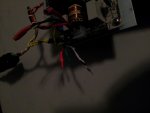
The IR filter is located behind the optical feedback and its mount(circular front of the laser, held in place by three bolts, with two wires comming out of it). and is just glued on the housing.
In your first picture you shifted the OF to the side, now there is another plate that you must remove to get to the filter. (two more bolts)

Removing this unit will reveal the IR filter, for some reason mine was dirty and upon removing the filter all together the output cleared itself up to a nicer profile. (before doing that my "dot" looked like some firework effect)

keeping the optical feedback off, will result in no regulation, which seems to make the laser output about 2X its running power (although more unstable, ive gotten ~30mw of mine and nothing failed.. so try running without it at your own risk)... but it can always be bolted back on after removal if you so desire.


Very good point, IIRC Dont lase me bro figured that out originally, but thats what I did to my unit also to correct the output after the profle was cleaned up by ridding of the dirty filter. (divergance wise, there is no collimators of any kind after the crystals)

http://laserpointerforums.com/f48/473nm-lab-pictures-65908.html

I got some pictures in that thread with the original output, and that after the removal of the filter and addition of a collimator.
 
Joined
Dec 11, 2011
Messages
4,364
Points
83
There are two wires that need to be shorted for it to turn on, but I can't remember their color or location or function because I made a jumper for it directly on the PCB when I got mine, I also removed all nonessential wiring. Just wanted to let you know that your laser might be fine and to not panic, good luck tracking it down!
 
Joined
Jan 30, 2012
Messages
2
Points
0
Thanks!

There is a red and green pair that is cut off, as well as a black and white, but I'm afraid to mess with it without a pinout or something. All three LEDs are on when I switch on the unit, except the laser is not turning on...

Thanks, I hope someone here knows and can help, mw


There are two wires that need to be shorted for it to turn on, but I can't remember their color or location or function because I made a jumper for it directly on the PCB when I got mine, I also removed all nonessential wiring. Just wanted to let you know that your laser might be fine and to not panic, good luck tracking it down!
 
Joined
Dec 11, 2011
Messages
4,364
Points
83
Yeah, the two wires I spoke of are for TTL blanking; having them shorted turns the pump diode on.

edit: I am taking a picture of mine for you: (I believe it is the black and white which need to be shorted together!)

Far left: Black shorted to White.
photo1dp.jpg


Relative Placement of connector: Note no Red/Green pair other than the AC input Hot/Ground leads (which are Red and Green/Yellow respectively). The two red leads on the top left go to the AC switch.
photo2uem.jpg


LED indicators:
photo3bh.jpg
 
Last edited:
Joined
Nov 4, 2011
Messages
801
Points
28
The balck and white go together. See picture.


Scott
 

Attachments

  • wire.jpg
    wire.jpg
    56.1 KB · Views: 306
Joined
Dec 11, 2011
Messages
4,364
Points
83
I just noticed the last realignment I did greatly increased the output power... see video:


Fiddy

0
Joined
May 22, 2011
Messages
2,726
Points
63
Wow nice, thats some decent power out of a 10mW factory claim!

Ive played with the alignment on mine for ages and rotated the crystal 180 degrees and the most i got out was 4mW, must have a bad unit.


Top