Welcome to Laser Pointer Forums - discuss green laser pointers, blue laser pointers, and all types of lasers

Buy Site Supporter Role (remove some ads) | LPF Donations

Links below open in new window

ArcticMyst Security by Avery | Browser Hide by Avery

B&W-tech Spectrometer & 473 module: Setup+Mods+Info

Re: B&Wtech 473nm unit / Spectrometer Mods & Info

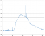
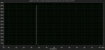
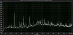
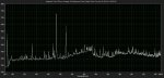
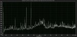
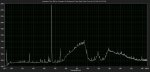
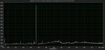
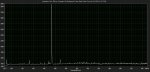
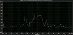
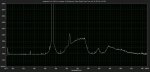
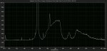
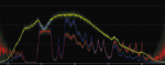
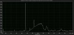
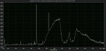
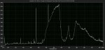
Wow, interesting results chloderic :beer:
Do you believe 473nm could also cause a small amount of fluorecense? I couldn't imagine the manufacturer over looking the fact that this could cause stray readings in the original units operation.

@chloderic, take a look at this company in Germany - https://laserpointerforums.com/f70/new-age-spectrometer-102773.html#post1528408

J :beer:

thanks for the link .... very interesting.
At the moment I prefer to work on something in and with this forum, a finished part has less appeal ...


Re: B&Wtech 473nm unit / Spectrometer Mods & Info

the developers of this unit have certainly not overlooked that, but in the planned application that was actually irrelevant, because if you look at the sticker on the devices and the listing of "left pixel" "right pixel" "left range" "right range ", it is clear that only a certain small target spectral range was interesting for a result. the rest of the disruptive fluorescence was indeed (as known) hidden by this baffels inside.

Hi, the part you quoted was a discussion about a power-suppy-cable , not an usb to rs232 converter .
but thanks for the link and your experience, that may help the others who are searching for that.

thanks for the link .... very interesting.
At the moment I prefer to work on something in and with this forum, a finished part has less appeal ...

Yes this makes sense, making the flourencent spectra irrelevant :D

@chloderic - btw, just to let you know you can "multi-quote" posts by selecting the multi-quote icon at the bottom of each post, then combine all your replies into one. Some members on LPF prefer this method so i thought i'd let you know now :beer: :D

Also you can edit your post, to add addition info, if you are the last poster in the thread :beer:

I too prefer to work on these b&w units as a community, its a better and more rewarding experience imo :D I believe new members have joined only due to this topic on LPF :)

J
 
Re: B&Wtech 473nm unit / Spectrometer Mods & Info

to explain what i mean i added a picture here, the open beam splitter is visible and the glowing spot is the fluorecenz in response to a 405 nm laser.

Dear ChlodEric,

But it is still strange to have the fluorescence @ 473nm the wavelength at which the spectrometer should work ... don't you think?
C
 
Re: B&Wtech 473nm unit / Spectrometer Mods & Info

Hello Civitus,

The spectra I posted were indeed captured with the setup you mentioned (at least the raman ones... the spark emission was without the beamsplitter). However, they are shown with background subtracted: take a reference spectrum without an empty bottle in front of the beamsplitter (or nothing in front if a solid material), with the exact same settings (exposure/averaging). Then mark, use the function "Use current spectrum as background" in Spectrum studio (button with green downward arrow). If you re-acquire a spectrum with the same setup, you should see a spectrum close to zero. Then, put your sample in front of the beamsplitter and acquire a new spectrum. You will see the delta from the previous one. In this way, you can get rid of for instance the fluorescence on the condition nothing (reference spectrum or raw spectrum from the sample) is saturated. The fact that the baseline on one of my spectra goes below zero is a result of a change in the background between the acquisition of the reference spectrum and the spectrum of the sample. Note that the files record both the background spectrum as the raw spectrum... if needed, you can still change the background spectrum when importing the data in for instance excel.

Chloderic, indeed, I noticed as well some fluorescence at the input port of the spectrometer (with the highpass filter still installed) and possibly even in the fiber optic cable (I saw the sleeve lighting up when using an intense laser in combination with a reasonably sharp bend in the cable).
 
Re: B&Wtech 473nm unit / Spectrometer Mods & Info

Dear ChlodEric,

But it is still strange to have the fluorescence @ 473nm the wavelength at which the spectrometer should work ... don't you think?
C

Yes, indeed, that's very strange. I am still looking for the reason for various effects and therefore describe my observations. maybe we will obtain results through various theories.
 
Re: B&Wtech 473nm unit / Spectrometer Mods & Info

Hello Civitus,

In this way, you can get rid of for instance the fluorescence on the condition nothing (reference spectrum or raw spectrum from the sample) is saturated. .

Dear diber,
So can I understand that you got also the strange and stromg fluorescence but you got ride of it just bytaking is a background signal that you substracted?
Thank you for your help

C
 
Re: B&Wtech 473nm unit / Spectrometer Mods & Info

Hello Civitus,

That's correct. I have attached the background spectrum from the isopropyl spectrum I have posted (got it out of the csv file with EXCEL). I also attach a picture of the setup... the background is taken with the empty bottle in front of the probe and then I filled the bottle with the alcohol (note that with the probe you use the backscattered configuration). Take care to connect the laser and the spectrometers to the right ports of the splitter, otherwise you loose too much signal. Finally, the spectrum was obtained with a spectrometer for which the long-pass filter was NOT removed (it attenuates the laser).
 

Attachments

  • Raman setup.JPG
    Raman setup.JPG
    116.5 KB · Views: 65
  • Background.png
    Background.png
    31.3 KB · Views: 52
Re: B&Wtech 473nm unit / Spectrometer Mods & Info

By the way, I designed a housing for the spectrometer in Fusion360 and 3D-printed it. Stand-offs are incorporated and short M3 screws screw straight in to hold the cover and the spectrometer (at least when printed on my printer). Reduces the fan-noise (glued some soft pads to the bottom to avoid the vibration noise), avoids light leaks (I had a small light leak after opening the spectro to remove the internal baffles) and makes it easier to handle.

If anyone is interested in the files, let me know and I will mail them (or if anybody can tell me how to attach for instance stl files, I will attach them here).

EDIT: link to the stl files: https://www.dropbox.com/sh/nty4b2hdf31fidg/AACujLNkkfGpkU-TT28plfrEa?dl=0
 

Attachments

  • Spectrometer housing cad.png
    Spectrometer housing cad.png
    262.2 KB · Views: 45
  • Spectrometer housing.JPG
    Spectrometer housing.JPG
    106.7 KB · Views: 50
Last edited:
Re: B&Wtech 473nm unit / Spectrometer Mods & Info

Because of the different problems with the fluorescence i have made a few attempts.
I spent some time with my 7 beam splitters and compared the 6 with intact dicro,
the 7th dicro was torn on delivery and is unusable.
First of all, as already indicated, there are different dicros with different properties installed.
This can be seen by the different colors (as well as the filters in the spectrometer), if you look through it.
3 in comparison, the colors range from bright yellow to green. see the attached picture.

Next i will post the different results with spectrumstudio,
here i used in all cases the same laser and the same lightfibers.
 

Attachments

  • 0.jpg
    0.jpg
    191.5 KB · Views: 44
Re: B&Wtech 473nm unit / Spectrometer Mods & Info

These spectra were recorded under the conditions described above with 6 different beamsplitters and show different behavior in the discharge of the laser radiation.
The dicros in the beam splitter thus reflect different and of course unwanted laser radiation into the spectrometer.
In this case the highband filter in the spectrometer is not installed.
 

Attachments

  • 1A.jpg
    1A.jpg
    119.7 KB · Views: 37
  • 2A.jpg
    2A.jpg
    119.5 KB · Views: 31
  • 3A.jpg
    3A.jpg
    119.5 KB · Views: 28
  • 4A.jpg
    4A.jpg
    117.9 KB · Views: 26
  • 5A.jpg
    5A.jpg
    119.8 KB · Views: 29
  • 6A.jpg
    6A.jpg
    119.7 KB · Views: 27
Re: B&Wtech 473nm unit / Spectrometer Mods & Info

In this pictureseries i have reinstalled the internal filter in the spectrometer under other identical conditions.
the worst use signal / rest laser ratio has probably the splitter nr 1,
the filter of nr 2 has the greatest fluorescence, the others are a bit "strange" ...
If I now want to use this entire assembly with this laser for Raman spectroscopy, i could not decide yet, which of these 6 beamsplitter is the most suitable for this, BUT it will goes on .....
 

Attachments

  • 5C.jpg
    5C.jpg
    133.3 KB · Views: 22
  • 6C.jpg
    6C.jpg
    126.9 KB · Views: 20
  • 4C.jpg
    4C.jpg
    132.9 KB · Views: 24
  • 3C.jpg
    3C.jpg
    124.7 KB · Views: 24
  • 2C.jpg
    2C.jpg
    124.4 KB · Views: 23
  • 1C.jpg
    1C.jpg
    121.7 KB · Views: 24
Re: B&Wtech 473nm unit / Spectrometer Mods & Info

I would measure the transmittance of each of them (f.i. take a spectrum of an incandescent lamp without/with the beam splitters) and look for the one that has the "flattest" curve above 500 nm as well as possibly the cut-off wavelength closest to the 473 nm. Once you know the curve, you can correct your acquired raman spectra for the specific transmittance curve.

By the way, I also have a yellow and several green beam splitters. First I thought that it was caused by a different alignment of the dichroic (for instance cut-off can be influenced by the angle), but looking at the spectra, there seems to be a big difference in transmittance in the 520 to 580 nm area. For instance, the "yellow" one blocks a lot (10 to 20% transmittance... this is the one I posted the characteristics of a few pages back) the areas around 540nm and 560 nm, while the green one passes it through very well. At first look (I just looked at the spectra, not at the transmittance curve), I would use the green one since it does not seem to have these deep dips in transmittance compared to the yellow one.
 
Re: B&Wtech 473nm unit / Spectrometer Mods & Info

To make a possible decision, i have produced a RAMAM-spectrum of a diamond, here is the dicro filter in the spectro removed.
Since the ramansignale are very weak, I zoomed in the level 1000 - 3000.
The peak at 472 is then the rest of the laser and in the range of 1332cm-1 shift is the expected main signal from the diamond (= about 505nm).
The visible waves to the right of the laser correspond to the annoying fluorescence.
After that I would say: 5 is garbage and 6 should be ok.

Here you see that the characteristic of the used components (i.E. beamsplitter) is very important.

BUT ... you can align them .... (a little bit) .
 

Attachments

  • 1B.jpg
    1B.jpg
    122.1 KB · Views: 30
  • 2B.jpg
    2B.jpg
    121.5 KB · Views: 28
  • 3B.jpg
    3B.jpg
    123.2 KB · Views: 27
  • 4B.jpg
    4B.jpg
    124 KB · Views: 24
  • 5B.jpg
    5B.jpg
    120.9 KB · Views: 25
  • 6.jpg
    6.jpg
    122.4 KB · Views: 28
Re: B&Wtech 473nm unit / Spectrometer Mods & Info

I would measure the transmittance of each of them (f.i. take a spectrum of an incandescent lamp without/with the beam splitters) and look for the one that has the "flattest" curve above 500 nm as well as possibly the cut-off wavelength closest to the 473 nm. Once you know the curve, you can correct your acquired raman spectra for the specific transmittance curve.

By the way, I also have a yellow and several green beam splitters. First I thought that it was caused by a different alignment of the dichroic (for instance cut-off can be influenced by the angle), but looking at the spectra, there seems to be a big difference in transmittance in the 520 to 580 nm area. For instance, the "yellow" one blocks a lot (10 to 20% transmittance... this is the one I posted the characteristics of a few pages back) the areas around 540nm and 560 nm, while the green one passes it through very well. At first look (I just looked at the spectra, not at the transmittance curve), I would use the green one since it does not seem to have these deep dips in transmittance compared to the yellow one.

Hi, nice to read you ... :) which lamp an which software did you use to measure the transmittance ?
 
Re: B&Wtech 473nm unit / Spectrometer Mods & Info

Just a normal "halogen lamp", but I am sure the standard household incandescent lamp is OK as well... even the sky is useable... you just need a source that gives a continuous spectrum in the area of interest. In order to determine the transmittance I used a self-written program, but you can do it as well in excel: for each wavelength divide the intensity acquired with the beam splitter by the reference intensity (the one without the beam splitter). Maybe you have to scale the reference if the setup is not exactly the same for both measurements in order to have it larger than the spectrum with the beam splitter... it will influence the absolute value of the transmittance, but not the shape of the curve. Note that this method becomes less and less accurate if the reference intensity is low... hence the need for a wide-spectrum source. I re-attach the curve I posted earlier (for the yellow splitter): yellow is the reference spectrum, without the beam splitter, blue is the spectrum acquired through the beam splitter (transmitted by the dichroic, not reflected) and red is the division between the two.
 

Attachments

  • BWTEK probe transmission port.png
    BWTEK probe transmission port.png
    133.5 KB · Views: 23
Re: B&Wtech 473nm unit / Spectrometer Mods & Info

Here is the 4th measurement:
I have now repeated the result of just now with the longed-pass filter in the spectrometer.
Accordingly, probably the combination number 6 most useful and the current adjustment of 5 in this form garbage.
BUT that's how I'm going to use this beam splitter no. 5 (also here garbage) to use for adjusting tests....
let's see what the turn of the components better comes out.
 

Attachments

  • 1D.jpg
    1D.jpg
    123.8 KB · Views: 21
  • 2.jpg
    2.jpg
    126 KB · Views: 21
  • 3D.jpg
    3D.jpg
    126.7 KB · Views: 19
  • 4D.jpg
    4D.jpg
    126.7 KB · Views: 18
  • 5D.jpg
    5D.jpg
    123.7 KB · Views: 19
  • 6.jpg
    6.jpg
    125.5 KB · Views: 23


Back
Top