Welcome to Laser Pointer Forums - discuss green laser pointers, blue laser pointers, and all types of lasers

LPF Donation via Stripe | LPF Donation - Other Methods

Links below open in new window

ArcticMyst Security by Avery

Any techniques for aligning a Z-fold cavity?

Joined
Dec 26, 2012
Messages
55
Points
18
I've been working on a DPSS laser for a while now. My goal is a frequency doubled Z-fold pumped by two 40w FAPs. I've done a ton of work on this, from designing my own power supplies and TEC controllers, to modeling the cavity via software to ensure stability and a decent beam waist in both the vanadate and KTP. This is my first "real" laser project, but I've done quite a lot of research and am making good progress.

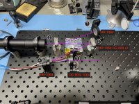
I've had success getting a simpler L-fold cavity to lase up to about 4 watts (of IR...I did get green to work but very weakly) and have been able to repeat my alignment technique for getting the L-fold aligned. But the Z-fold is a whole different ball game. On the L-fold I had six spots to worry about: Three spots from front and back reflections of the resonator fold mirrors, and this was doubled by some refraction happening in the vanadate. On my Z-fold layout I have three fold mirrors, gobs of spots and the light from my HeNe isn't intense enough to be visible through a round trip (or I'm off so far I can't see where the spots are going).

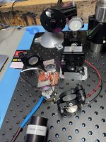
Here is a photo of my layout with the mirrors numbered and annotated:
IMG_0727s.jpg

I started by replacing fold mirror #3 with OC #5 and aligning to get the L-fold lasing. Then I put fold mirror #3 back and I replaced mirror 5 with a pinhole and re-set my alignment laser to point into the cavity through the pinhole. I can get spots shining all the way back to mirror #1, but I just can't see anything coming back at the pinhole. Actually, I don't think my idea of getting the 1-2 arm of the L-fold aligned means much, since fold mirror 3 has no guarantee of following the exact same path.

Anyone done this? I'd sure like to learn some techniques.


Anthony P

Well-known member
Joined
Oct 7, 2018
Messages
529
Points
63
While I have never attempted anything this complex, I have aligned many 2 mirror HR/OC resonators. If I were trying to tackle this one, I would start with "boresight" of alignment laser through crystal. Then remove #5 and replace it with a screen or card some distance away. Obviously adjust your steering mirrors, then 1 and 4 until you get a shimmering spot on card ( sometimes called dancing fringes). replace 5 and adjust until fringes return. Turn on your whole system to tweek 5. Pick one adjustment screw on your kinematic and leave it alone. Pan second screw + and- about 90 deg. If no output appears, return screw 2 to start and turn screw 3 , 1 or 2 deg. Then pan 2 again. repeat until a flash of laser light appears. Tweak to max output.
A different color alignment laser may help. I generally use a green diode. There is such a thing as an alignment laser that is too bright, though.
Any laser alignment procedure should start with going to the store to purchase a minimum of 6-12 beers. Good luck to you! Hope this helps.
-Tony
 
Last edited:

kecked

0
Joined
Jun 18, 2012
Messages
952
Points
63
good Luck following. I assume #2 is a lens? If not you likely need one to get the density right in the crystal. Also make sure the polarizations make sense.
 
Joined
Dec 26, 2012
Messages
55
Points
18
good Luck following. I assume #2 is a lens? If not you likely need one to get the density right in the crystal. Also make sure the polarizations make sense.
#2 is a planar mirror that's HR 1064 HT 808. But the black cylinder to the left is a combination collimator and focusing assembly. It's currently set to about 300um but with a lens swap I can get it down to about 150um at the crystal face. Unfortunately the light coming into this is a fiber coupled FAP with random polarization. It works, but it would be more efficient if it was polarized.
 
Last edited:
Joined
Dec 26, 2012
Messages
55
Points
18
While I have never attempted anything this complex, I have aligned many 2 mirror HR/OC resonators. If I were trying to tackle this one, I would start with "boresight" of alignment laser through crystal. Then remove #5 and replace it with a screen or card some distance away. Obviously adjust your steering mirrors, then 1 and 4 until you get a shimmering spot on card ( sometimes called dancing fringes). replace 5 and adjust until fringes return. Turn on your whole system to tweek 5. Pick one adjustment screw on your kinematic and leave it alone. Pan second screw + and- about 90 deg. If no output appears, return screw 2 to start and turn screw 3 , 1 or 2 deg. Then pan 2 again. repeat until a flash of laser light appears. Tweak to max output.
A different color alignment laser may help. I generally use a green diode. There is such a thing as an alignment laser that is too bright, though.
Any laser alignment procedure should start with going to the store to purchase a minimum of 6-12 beers. Good luck to you! Hope this helps.
-Tony
Thanks Tony. Will spend a few nights this week trying this out. Your green laser sparked an idea -- I have a cheap DPSS 532nm laser that spits out a bunch of 1064 light too. I have not been using it for alignment because while the label says < 5mw, my LPM says it's putting out about 60: way too much for unprotected eyes. I could filter out the 532 and only leave the 1064 and see the spots through my IR camera. This should make the spots on the cavity very obvious, and since the mirrors are designed to reflect 1064 I should have much brighter spots to look at.

Are you thinking I send the alignment laser through the steering mirrors (1 or 3) as if it were the pump diode? I have been sending it through the OC (removing the OC first and replacing with a pinhole). On my L-fold setup when it's aligned the HeNe starts to flicker a bit -- probably similar to your dancing fringes.
 
Joined
Dec 26, 2012
Messages
55
Points
18
I've spent some time on this and no luck. First, my idea of using the IR leakage from my 532nm pointer is not going to work. Yes, it's cheap and leaks IR. But is just "spill" from spontaneous emission and not in the beam. If I put a visible block filter in front of it I get next to nothing on an IR card. So that's out.

I have had some luck using the 532 for alignment. It's much brighter than my HeNe. It's not eye safe, but I have some IR detector alignment targets that have a hole through them, and the 532 does cause the target to glow a little bit. But it's still not great.

I've decided to take a step back. I have gotten a successful alignment of an L-fold cavity, but I've never been able to make a linear configuration lase. This makes me think I just got lucky the first time and now I "know where to look" to repeat it. I really want to make that linear cavity lase to help ensure I know what to look for.

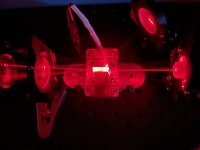
I am hoping someone here who has done this with a DPSS laser can help explain what I'm seeing. If I align with the crystal mounted, the crystal wildly changes the angle of the HeNe beam. The angle change is much more than what I would expect from refraction if the crystal was not perfectly parallel. I've attached a photo of what I'm seeing. The HeNe beam enters from the right side of the crystal. When it leaves the left side it deviates from center by what looks like about 5 degrees. It has also produced more than one beam, although clearly one is dominant. Why? Do I need to severely skew my HR mirror to match this angle and reflect it back? I've searched and searched but not read about this anywhere. This makes aligning very difficult. I can align easily without the crystal in place, but I can't get any lasing with the crystal in place no matter how much I tweak the mirrors. I didn't notice this with the L-fold setup because there are multiple reflections due to the interplay between the HR and the fold mirror.

Oh, and that mirror above the crystal that has a line of red on it is not being used. It's part of my L-fold setup but the mirror on the left is positioned for a linear cavity. The L-fold mirror is just picking up stray reflections from the crystal mount.

TIA for any insight.

IMG_0779.jpeg
 
Joined
Jun 4, 2012
Messages
17
Points
3
First and foremost I am no expert.

What brand FAP modules are you using? In certain applications fiber termination can make a difference. i.e. are they dirty, polished, cut angle etc.
What is the setup of your collimation and or focusing optics? And are they corrected? NA , EFL? Once again, maybe not critical in all applications but these things do add to error. Horizontal/Vertical Tilt, Defocus, and Astigmatic aberrations can cause strange problems and are quite difficult to diagnose.
Are you using flat or curved mirrors?

On alignment: if you are dealing with beams that are not visible the cheapest option would be to use something like ZAP-IT paper in some type of mount that keeps it perpendicular to the breadboard. You can always cut it to a size just over your beam diameter and hold it with tweezers. The easier, albeit more expensive alternative is a beam profile camera (if using high wattage lasers) or a CCD camera with a sensor material for your particular wavelength and a free software like Beam Profiler (wattage under damage threshold for a sensor.)

Have your measured temperature of the crystal? Try heating it up or cooling it down and see if anything changes. Did you calculate needed crystal size, and corresponding conversion efficiency etc.? That last picture looks like "spatial walk-off". Check the polarization both pre and post cavity ( or in your case both of the beams post.) You may have stumbled into a critical phase matching regime where the range of acceptance angles (phase-matching bandwidth if you're an "academic") becomes increasingly smaller in order for you to get your intended result. Little things like Raleigh Scattering, how Gaussian is your beam, parasitic reflections, and so on then become the answer to your original question. A two axis translation stage with your collimating optics mounted on top helps alleviate any dependencies on the tolerances of the holes drilled into your breadboard.
 

kecked

0
Joined
Jun 18, 2012
Messages
952
Points
63
Summary go buy a finished module and enjoy your hair growth.
 
Joined
Dec 26, 2012
Messages
55
Points
18
:) Ha. Been there, done that. I have plenty of things that pew pew. This one...this is more of a journey. And my wife hoping someday I will talk about something else.

whysoserious - FAPs are Coherent FAP 40w. They are used but in good condition and temperature tuned to emit @ 808. I don't intend to drive them fully. Fibers are recommended Coherent fibers: 800um, AR coated, .16na. Collimation is done through a 125mm EFL PCX lens which gives a collimated beam about 22mm in diameter and that goes into a 75mm PCX to focus into the crystal at 400um. It's a little large for the mode volume (about 2x) but more forgiving on alignment. I have a 50mm lens ready to go that will get me to about 300um, but I want to wait until I have light from the cavity so there are fewer things to adjust. I also have the pump input mounted in a shear plate so I can make micro adjustments to the alignment (+- 1mm X / Y).

Mirrors in the linear arrangement: HR is planar and the OC is curved with a ROC of 1m. It's not quite a hemispherical cavity because the cavity is shorter than the EFL of the OC. I'm using the open source software Rezonator to calculate cavity stability and this arrangement is stable.

When I have a beam, I have high power IR card viewers that I can use to fix minor alignment issues. For example, I can see it cycle through different modes. Without it lasing there is sufficient pump intensity at the crystal face for it to glow a bit so I've been using that to align pump and HeNe beams.

Crystal is held in a TEC @ 25 degrees C but I can certainly try changing this to see if it has any effect. But here, I'm just trying for initial alignment with a 5mw HeNe and the intensities should be small. I am aware of spatial walk off for non-linear crystals but I've not read about it in Nd:YVO4, and this is a surprisingly large angle, especially for such a low intensity beam. I have a 1/2 waveplate I can use to rotate the polarization of the HeNe (actually I don't even know if this HeNe produces polarized output. Probably good to check that anyway).

I have calculated stability parameters for the cavity and the expected mode volume, but I have not calculated the required pump power to reach threshold. That's something I have been reading up on but I'm not quite there. I know in the L-fold configuration it lases at about 7w of incoming pump light with an output of about 2w.
 
Joined
Jun 4, 2012
Messages
17
Points
3
The brand of laser module doesn't matter all that much, but I was making sure it wasn't some cheap no-name Chinese module because it would have likely been the root of all your problems. Changing the temp of the crystal also shouldn't do much; but if you see something drastic it would point towards instability and a potential critical phase matching issue. Same with beam size and collimating optics, if increasing spot size on the first crystal surface saw an improvement, it would give you insight into the instability and phase issues.

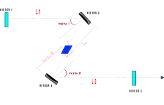
I had to go back to some of my notes when I was playing around with Z-folding: here are two diagrams I quickly drew up (not my findings, just notes from others' research.)

z fold layout.png

When L1 & L2 are not the same length you get four stable boundary regions, defined by both tangential and sagittal planes:

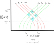
boundry curves z fold.png

I know the equation in the 2nd chart for Z distance is analytically incorrect but I simply wanted to keep the notation between the two images continuous. Basically you can say the distance between mirror 3 and first crystal surface 1 is L3, and send crystal surface 2 and mirror 4 is L4; therefore Z = L3 + L4.

- If you increase the focal length of the fold mirrors, boundaries B1, B2, B3, B4 will shift to the right and thus increase total z distance. B2 & B4 increase faster than the rest which results in a widening of the 4 boundary regions.
- B1 is completley independent of L1 & L2.
- An increase in the length of L1 shifts both B3 & B4 to the left at equal rates which results in stable region II (2) having the same area.
- An increase in the length of L2 shifts B1 & B2 to the left which results in a decrease in stable regions I (1) and II (2)
- In a completley stable configuration a change in L(c) (or L3 as mentioned earlier) either increase or decrease should not effect overall stability within cavity.
- If L1 & L2 are equal, two of the boundary constraints disappear so long as the crystal size is within T(minimum) and T(maximum).

TLDR: by changing L1 & L2 distances you can impose boundary constraints that should help you non-analytically map out where your maximum values are. There are enough constraints that they should overlap each other in the sense that you can change one value, write it down & check if it satisfies the rules. If that value does not, then it would be in an instability region. Without micrometers on your mirrors, simple 1 turn - 1/2 turn - 1/4 turn etc. to the left or right measurements should do just fine. If you are unable to define at least two stable boundary regions then it its likely the size of your crystal that's causing instability.
 
Joined
Dec 26, 2012
Messages
55
Points
18
Thanks for this, it's great data and will come in handy as I dial in the z-fold. I figured out my alignment confusion. Well, I got some help from folks along the way. The alignment beam is going to deflect from the crystal for all sorts of reasons (crystal not totally parallel, refraction, birefringence, etc), so yeah, just go with the physics. The reason why it wasn't aligned after I "aligned" it is the refractive index change caused by the difference in wavelength between the alignment laser and the lasing fundamental. The deflection angle in the crystal is going to be different for 632nm and 1064nm, just like a prism refracts different wavelengths at different angles. In my case it's about .01º, or about 1.5 turns of a mirror adjustment screw.

Armed with this realization I got the linear cavity aligned and lasing in about five minutes.
 

Anthony P

Well-known member
Joined
Oct 7, 2018
Messages
529
Points
63
Glad to hear it. Next time you will be able to do it in 30 min.
 
Joined
Dec 26, 2012
Messages
55
Points
18
What do you plan for it?
(Sorry, totally misread your question).

No specific plans other than to learn how to do it and see what kind of power level I can achieve. I will frequency double it to green, and I want to try passive Q-switching once I understand enough to be reasonably confident I'm not going to ruin everything. I am hoping for several watts of 532 CW but I haven't done any real math to see if that's feasible.
 
Last edited:
Joined
Dec 12, 2012
Messages
854
Points
63
Congratulations on getting the Z-fold lasing. 🍺

Most dpss alignment I've ever done was on an educational system, standard linear arrangment, 808->1064->532, So I can't really help.


Top