Pman
0
- Joined
- Nov 28, 2012
- Messages
- 4,441
- Points
- 113
All batteries have their place. It just depends upon how they are applied.
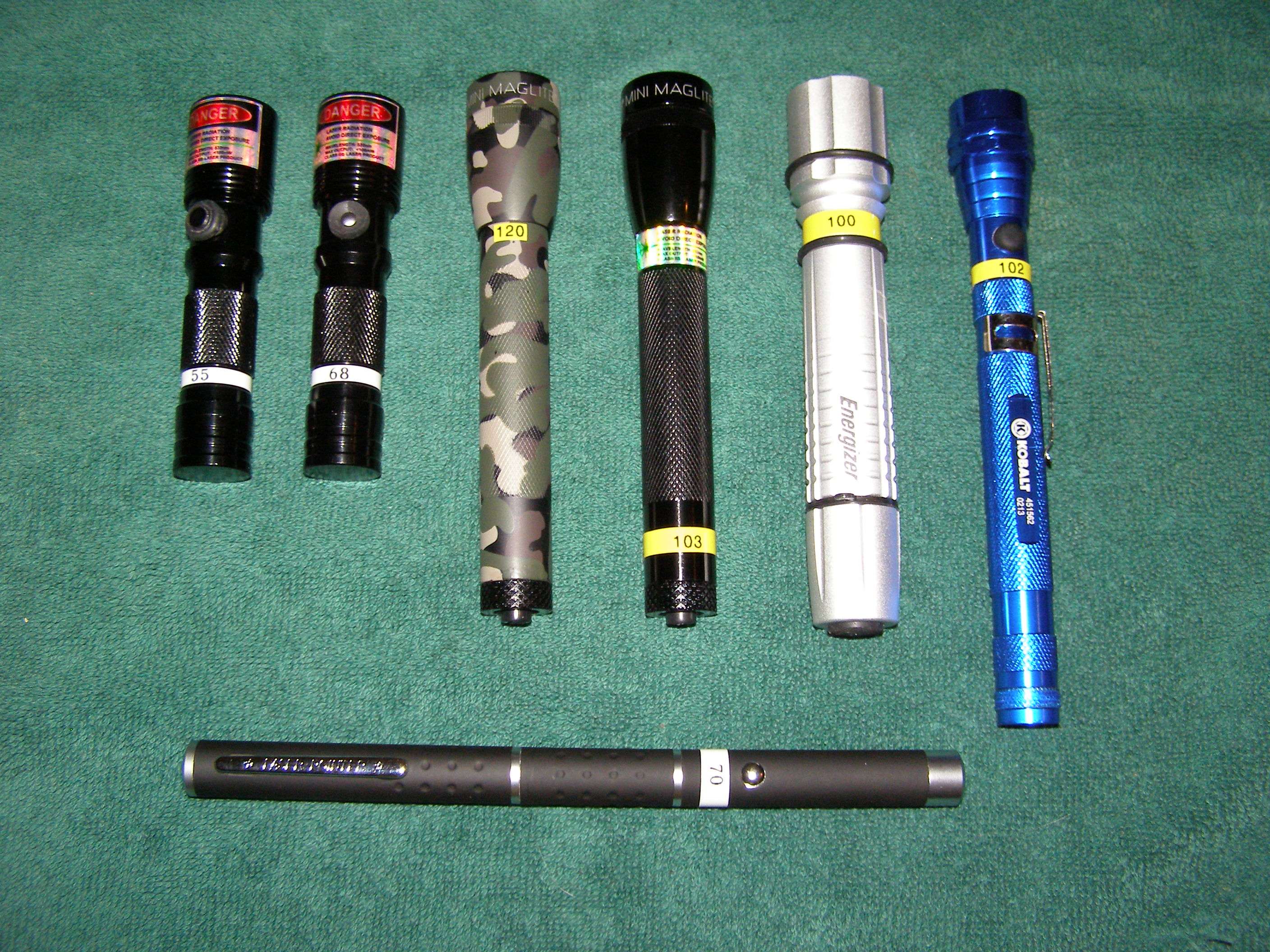
Stupid extra long pen I put together (because I could, that's why ) running off (3) 1.2V cells and it is an optical illusion that it is bent:
[URL=http://imageshack.com/i/f5fwslj] Uploaded with ImageShack.com[/URL]
[URL=http://imageshack.com/i/2o9litj] Uploaded with ImageShack.com[/URL]
As far as voltages go and units, you just need a variable DC power supply and LPM to really get an idea of where you are at. For example...
Over time messing with over a 100 3V and 5V Fasttech modules my procedure for pushing the envelope on them is to set the pots for a .43amp draw at 3.2V and then start testing outputs and adjusting the pot down from there if necessary. Some modules eat it up and have output over 140mw while others will only run somewhat stable (remember we are talking specifically about 532nm here) at about .28amps which is around where they are originally set although I've seen them set all over the place.
Then I ramp up the voltage on the 3V ones to 4.2 and make sure everything is still OK (not an issue with the 5V units).
This is the way I specifically mess with those modules. Doesn't matter to me if others would do it differently. This is the way I like to do it
I've got plenty of old soldering irons. I have one of those 405nm on hand that no works form me messing with trying to get the epoxy off so it looks like I have a guine pig
Stupid extra long pen I put together (because I could, that's why
[URL=http://imageshack.com/i/f5fwslj]
 Uploaded with ImageShack.com[/URL]
[URL=http://imageshack.com/i/2o9litj]
 Uploaded with ImageShack.com[/URL]
As far as voltages go and units, you just need a variable DC power supply and LPM to really get an idea of where you are at. For example...
Over time messing with over a 100 3V and 5V Fasttech modules my procedure for pushing the envelope on them is to set the pots for a .43amp draw at 3.2V and then start testing outputs and adjusting the pot down from there if necessary. Some modules eat it up and have output over 140mw while others will only run somewhat stable (remember we are talking specifically about 532nm here) at about .28amps which is around where they are originally set although I've seen them set all over the place.
Then I ramp up the voltage on the 3V ones to 4.2 and make sure everything is still OK (not an issue with the 5V units).
This is the way I specifically mess with those modules. Doesn't matter to me if others would do it differently. This is the way I like to do it
I've got plenty of old soldering irons. I have one of those 405nm on hand that no works form me messing with trying to get the epoxy off so it looks like I have a guine pig
Last edited:


