- Joined
- Feb 25, 2010
- Messages
- 9
- Points
- 0
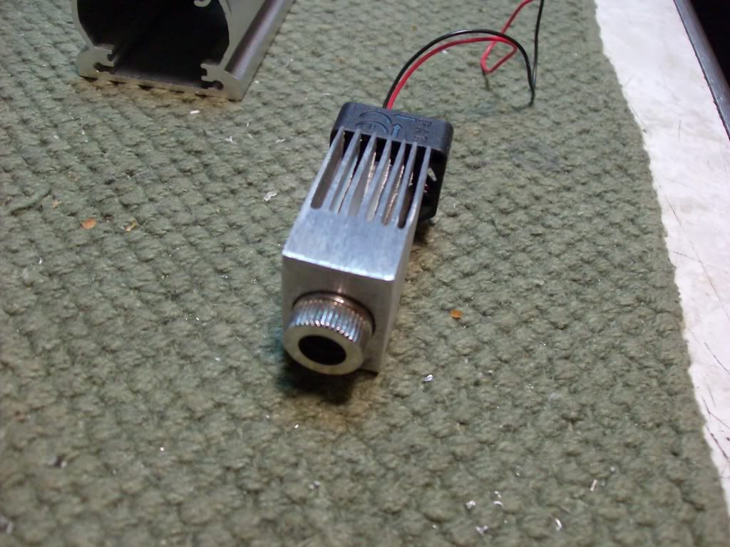
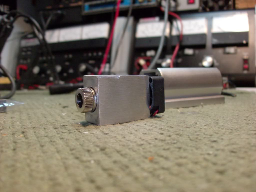
Ok so I bought this laser Diode/Driver. It came with schematics and everything made to build it. Below I included the images. I need help with What kind of power i need to give it. Thanks.
Also i will include the description so that you can determine a accurate power supply.


300mW+ 650nm Red Burning Laser Diode Module with Adjustable Lens
10 part precision Adjustable Constant Current about 100mA to 463mA routed PCB Driver DIY kit with protection circuit included.
Also include Heat Sink for LM317 and Laser Diode Module.
Already routed Professional PCB DIY Kit cannot compare with other seller's amateur kit.
You are bidding on a precision new Single Mode Red 650nm long die open can laser diode module.
Long die open can laser diodes are rated for Class IIIb 300mW+ @650-670nm CW extract from new(never used) DVD Bunner Driver.
This long die open can diode have been probed to be very stable at high power output ranging from 300mW+.
This is long die open can diode so they are extremly fragile therefore must very careful to open lens and must use proper heat sink for high power drive.
The ideal use of this open can diode is 250mW CW at 420mA with acrylic lens( 300mW with glass lens).
Max Output : 300mW+
Max Current : 500mA
Threshold Current : ~80mA
Module : 12mm diameter x 30mm length
Lead wire 30cm(Red plus[+], Black minus[-]) with 2.5mm pitch Connector.
ALL : Assembled and inspected from licenced company.
PCB can change without notice for improvement.
Constant current driver kit include some safety circuit for laser diode protection- 9 part with Heat sink for LM317 and Laser Diode Module .
Circuits included some filter, max current limit(about 463mW) for protect from over current, capacitor discharge and reverse current protection.
Maximum current limit resistor can remove but I don't recommand because it's make easy kill your diode.
I ship copy of driver schematic and layout for easy place parts.
Thanks in advanced to anyone that helps me!!!
Also i will include the description so that you can determine a accurate power supply.
300mW+ 650nm Red Burning Laser Diode Module with Adjustable Lens
10 part precision Adjustable Constant Current about 100mA to 463mA routed PCB Driver DIY kit with protection circuit included.
Also include Heat Sink for LM317 and Laser Diode Module.
Already routed Professional PCB DIY Kit cannot compare with other seller's amateur kit.
You are bidding on a precision new Single Mode Red 650nm long die open can laser diode module.
Long die open can laser diodes are rated for Class IIIb 300mW+ @650-670nm CW extract from new(never used) DVD Bunner Driver.
This long die open can diode have been probed to be very stable at high power output ranging from 300mW+.
This is long die open can diode so they are extremly fragile therefore must very careful to open lens and must use proper heat sink for high power drive.
The ideal use of this open can diode is 250mW CW at 420mA with acrylic lens( 300mW with glass lens).
Max Output : 300mW+
Max Current : 500mA
Threshold Current : ~80mA
Module : 12mm diameter x 30mm length
Lead wire 30cm(Red plus[+], Black minus[-]) with 2.5mm pitch Connector.
ALL : Assembled and inspected from licenced company.
PCB can change without notice for improvement.
Constant current driver kit include some safety circuit for laser diode protection- 9 part with Heat sink for LM317 and Laser Diode Module .
Circuits included some filter, max current limit(about 463mW) for protect from over current, capacitor discharge and reverse current protection.
Maximum current limit resistor can remove but I don't recommand because it's make easy kill your diode.
I ship copy of driver schematic and layout for easy place parts.
Thanks in advanced to anyone that helps me!!!


