Welcome to Laser Pointer Forums - discuss green laser pointers, blue laser pointers, and all types of lasers

LPF Donation via Stripe | LPF Donation - Other Methods

Links below open in new window

ArcticMyst Security by Avery

2A driver circuit ... Need help

Joined
Aug 30, 2015
Messages
6
Points
0
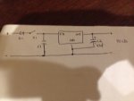
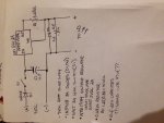
I know a lot of people buy drivers but I'm more interested in the electrical circuitry in building lasers . I recently built a 0.8mA red laser and a 1.25A blue laser with a m140 diode. I want to build a driver that can operate at 2.0A because these m140s can be pushed to 1.8A comfortably . The lm317t is only capable of 1.5A output so I bought a NTE1934 capable of 5V 2A output . I would like some sort of schematic before I attempt to build this . I have pictures of my drawings but can't figure out how to post them on here I can email them to anyone willing to help thanks


OVNI

2
Joined
Oct 16, 2015
Messages
467
Points
0
According to this post from Cyparagon and his follow-up answer a few posts down, you can simply wire two of your 1.5A circuits in parallel resulting in a 3A driver. They will load share due to being configured as a constant current source.

I don't know Cyparagon but from what I've read, he knows what he's talking about. And if I have it wrong, I'm sure we'll find out. It's an easy enough circuit if you want to build/test but doing some analysis would go a long way too.

From DTR's test data on his website, the voltage across the M140 at 2A was 4.7V. If the NTE1934 is only capable of driving 2A at 5V you will likely need more voltage to drive an M140. I doubt 0.3V is enough headroom. Cyp may be able to tell you off the top of his head how much more voltage is required or there are several other folks here with an electronics background.

Feel free to PM or email me your schematic. I'll pull the datasheet for the NTE1934 and take a look. There may be a better part for your application and I suspect someone here already knows what it is.
 
Last edited:
Joined
Aug 30, 2015
Messages
6
Points
0
the first image(without material list) is what Is suggested by the manufacturer of the nte1934. the second image with the material list is the one I designed based off of my research and knowledge of the last two drivers I built. some clarification would be great thank you
 

Attachments

  • IMG_0628 (600x450).jpg
    IMG_0628 (600x450).jpg
    135.6 KB · Views: 63
  • IMG_0627 (600x800) (450x600).jpg
    IMG_0627 (600x800) (450x600).jpg
    156.1 KB · Views: 73

diachi

0
Joined
Feb 22, 2008
Messages
9,700
Points
113
You can use an LM338 to provide 2A. Specs and schematics for constant current are similar to the LM317 except the LM338 is good for 5A.

Or two LM317s in parallel...
 

OVNI

2
Joined
Oct 16, 2015
Messages
467
Points
0
Your first picture, as you probably know, is a (constant) voltage regulator. The second picture is a constant current source for a 1.8A supply. So far so good. Some notes:

1) At 1.8A the 0.68 ohm resistor is dissipating over 2W. Make sure the resistor power handling capability can handle it. You may want to use a heatsink or something like this.

2) According to DTR's website, at 1.8A the M140 runs at around 4.6V leaving a 0.4V margin. That may be enough but I suggest doing more research on the LD (or someone here might know). To test the driving capability, you could try breadboarding it using a dummy load (instead of your laser diode) consisting of 4 of the 1N5408 diodes in series.

3) At 1.8A the voltage drop across the 0.68 ohm resistor is ~1.2V. Therefore the regulator chip you select must be capable of delivering ~6V (4.6V+1.2V).

4) Per diachi's suggestion, using an LM338 instead of the NTE1934 means you only need the one circuit as shown in picture 2. From TI's spec, the headroom required appears to be >3V so with 6V needed at the output, a 9V input just makes it.

HTH
 
Last edited:
Joined
Sep 12, 2007
Messages
9,399
Points
113
NTE1934 is a 5V regulator. Therefore the voltage between pins OUT and GND will be driven to 5V if possible. Not the 1.25V of an "adjustable" regulator. That means 7.35A of current. The over-current protection will kick in, and the regulator will shut down. The resistor will be dissipating 37W before it does.

In short, your choice of IC will not work. Get something with a 1.25V Vref.
 
Joined
Aug 30, 2015
Messages
6
Points
0
Hey guys thanks a lot for all the responses , OVNI thanks for the detailed response that helped a lot. I decided to abandon the nte1934 and built 2 lm317t drivers in parallel set at 0.9A each giving me the desired 1.8A capability for the m140.
 
Joined
Aug 30, 2015
Messages
6
Points
0
Your first picture, as you probably know, is a (constant) voltage regulator. The second picture is a constant current source for a 1.8A supply. So far so good. Some notes:

1) At 1.8A the 0.68 ohm resistor is dissipating over 2W. Make sure the resistor power handling capability can handle it. You may want to use a heatsink or something like this.

2) According to DTR's website, at 1.8A the M140 runs at around 4.6V leaving a 0.4V margin. That may be enough but I suggest doing more research on the LD (or someone here might know). To test the driving capability, you could try breadboarding it using a dummy load (instead of your laser diode) consisting of 4 of the 1N5408 diodes in series.

3) At 1.8A the voltage drop across the 0.68 ohm resistor is ~1.2V. Therefore the regulator chip you select must be capable of delivering ~6V (4.6V+1.2V).

4) Per diachi's suggestion, using an LM338 instead of the NTE1934 means you only need the one circuit as shown in picture 2. From TI's spec, the headroom required appears to be >3V so with 6V needed at the output, a 9V input just makes it.

HTH

In regards the 4 diodes in series will I need anything else to make a reliable dummy load ? Or will the 4 in series be sufficient ?
 

diachi

0
Joined
Feb 22, 2008
Messages
9,700
Points
113
Hey guys thanks a lot for all the responses , OVNI thanks for the detailed response that helped a lot. I decided to abandon the nte1934 and built 2 lm317t drivers in parallel set at 0.9A each giving me the desired 1.8A capability for the m140.


Someone correct me if I'm wrong, but I don't think that's how LM317s in parallel work ... As far as my understanding goes you'd set it up the same as you would with one, with a resistor setting the current at 1.8A and then you'd add another LM317 in parallel with the existing one - no extra resistors or anything.
 
Joined
Sep 12, 2007
Messages
9,399
Points
113
OUT pins need to be isolated for them to share the current. Therefore, two set-point resistors are needed as well.
 

OVNI

2
Joined
Oct 16, 2015
Messages
467
Points
0
NTE1934 is a 5V regulator. Therefore the voltage between pins OUT and GND will be driven to 5V if possible. Not the 1.25V of an "adjustable" regulator. That means 7.35A of current. The over-current protection will kick in, and the regulator will shut down. The resistor will be dissipating 37W before it does.

In short, your choice of IC will not work. Get something with a 1.25V Vref.

Good catch ... that's just :yabbem: to have missed.


Top