- Joined
- Aug 25, 2010
- Messages
- 37
- Points
- 0
Hahaha omg I have to share this with you guys, it totally cracked me up...
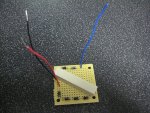
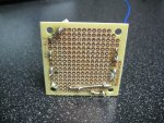
I killed my first blue diode last week, and not wanting to be held back in completing my build, I kept working on structural issues and heat dissipation issues. All seemed "ok", but in order to really give it a decent thermal test, I needed a diode in there. Since I don't have my replacement blue diode yet, I decided to build myself a dummy load as described in this thread. I carefully soldered five 1N4001 diodes, end to end, minding the anode and cathode markings (it's early and my mind is foggy, so I had to be extra careful), and finished them off with a single 1 ohm resistor. I built the little strip in a side to side type config to limit size and lead length (inductance may not even enter in, but I wanted to be sure). I soldered this neat little diode array to the leads for the laser diode, and placed my DMM between Vcc and the "hot" lead of the driver board.
I saw the amperage peg the 1.25A that I have the driver set to max out at, and watched it because without adequate heat elimination, the LM350 based design begins to cut itself off to avoid self destruction, and my recent efforts have been aimed at reducing or even eliminating this effect. I was pleased to see that the amperage only fell a couple of tens of mA over about ten seconds, which is a lot better than it was doing, but I started to smell something very hot anyway... and I thought, "But... the 350 is sinked! And... the current readings show that..." About this time, a sudden motion at the laser head caught my eye and I saw what the problem was right away.
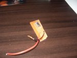
The two middle most diodes in the array got SO hot that they actually melted their solder joints and flopped forward as a pair to rest against the casing of the laser, lol! Wowwwwww... Well... I'm impressed! I figure I was only pushing about what, five watts or so through the array, but apparently that's more than enough to generate hot spots capable of melting solder. I don't know yet if I blew any of the diodes, but I wouldn't be at all surprised if I have.
Anyway, found that one amusing and thought some of you might get a laugh and/or some use out of that little experience.")
PS: A little update - I just checked the diodes and they appear to be fine... I get a voltage drop of about 0.57 to 0.58 on each, and no reverse flow at all. Tough little buggers!
I killed my first blue diode last week, and not wanting to be held back in completing my build, I kept working on structural issues and heat dissipation issues. All seemed "ok", but in order to really give it a decent thermal test, I needed a diode in there. Since I don't have my replacement blue diode yet, I decided to build myself a dummy load as described in this thread. I carefully soldered five 1N4001 diodes, end to end, minding the anode and cathode markings (it's early and my mind is foggy, so I had to be extra careful), and finished them off with a single 1 ohm resistor. I built the little strip in a side to side type config to limit size and lead length (inductance may not even enter in, but I wanted to be sure). I soldered this neat little diode array to the leads for the laser diode, and placed my DMM between Vcc and the "hot" lead of the driver board.
I saw the amperage peg the 1.25A that I have the driver set to max out at, and watched it because without adequate heat elimination, the LM350 based design begins to cut itself off to avoid self destruction, and my recent efforts have been aimed at reducing or even eliminating this effect. I was pleased to see that the amperage only fell a couple of tens of mA over about ten seconds, which is a lot better than it was doing, but I started to smell something very hot anyway... and I thought, "But... the 350 is sinked! And... the current readings show that..." About this time, a sudden motion at the laser head caught my eye and I saw what the problem was right away.
The two middle most diodes in the array got SO hot that they actually melted their solder joints and flopped forward as a pair to rest against the casing of the laser, lol! Wowwwwww... Well... I'm impressed! I figure I was only pushing about what, five watts or so through the array, but apparently that's more than enough to generate hot spots capable of melting solder. I don't know yet if I blew any of the diodes, but I wouldn't be at all surprised if I have.
Anyway, found that one amusing and thought some of you might get a laugh and/or some use out of that little experience.
PS: A little update - I just checked the diodes and they appear to be fine... I get a voltage drop of about 0.57 to 0.58 on each, and no reverse flow at all. Tough little buggers!
Last edited:


 )
)