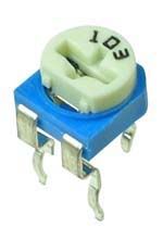
1 and 3 are either end of the resistive track, 2 is the wiper. How it works is there is a carbon track in the pot that from one end to the other is the full measured resistance (between 1 and 3). A metal contact is attached to the rotating portion that moves across this track (pin 2) and can divide the resistance such that if it was turned "half-way" on a linear pot, resistance between 1/2 and 2/3 would each be half of the total since the wiper is at the half-way point on the track.
Anyway, since you only need a variable resistance, not a voltage divide, you only need to connect two of the pins. You'll always want to connect pin 2, but the other pin depends on how you want the resistance to change as you turn the adjuster. If you want the resistance to decrease as you turn clockwise (which is the most common choice) you'll use pin 2 and 3. There is no polarity, so you can connect pins 2/3 in whatever orientation is easiest.
Make sure you also have a resistance in series with the pot, otherwise if you turn it too far, your resistance will drop very low and probably put out way too much current damaging your driver components or the laser diode. Also be aware that your pot is probably rated for 1/4W and you shouldn't use it to power much more than 500mA.


