

sam1902
New member
- Joined
- Dec 18, 2020
- Messages
- 5
- Points
- 1
Hello,
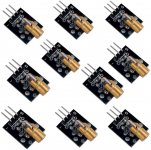
I'm making a laser triggered electronics project and I'm using one of those Arduino laser diode module to emit the laser (c.f. images). The specifications says it works on 5V and has a power of 5 MW (though I think they meant mW or else I'll have other problems). They also indicate that it has a power of 650nm and an OD of 6mm.
I don't know why they said OD was 6 mm as it doesn't seem to be a mesure of distance.
Upon powering the laser with my USB powered Arduino Uno, I thought the laser was quite powerful (compare to a simple presentation laser pointer) so I tried mesuring the tension and intensity it was using. I also measured it when powered through my Arduino Nano over USB, and to the same Arduino Nano on a 9V battery. I got the following reading off it:
From these result, I concluded that I had a Class 3B laser (5 to 500 mW) and after reading a bit about it, it seems I need to wear laser goggle protection so I ordered a pair of these which are rated for 190-470 and 610-760nm at OD 4+ (google for MCWlaser Lunettes de Protection Laser Safty Lunettes 190-470 & 610-760 nm).
This laser diode being a standard mass produce arduino module, I was a bit astonished by getting the above readings. So my questions are the following:
Are my readings realistic and is that the proper way to know the "power" of a laser ?
I'm only reading the electrical input to the diode, not the beam power itself because I only have a multimeter, not a spectroscope or anything fancy.
Is that protection adapted for that laser ? It's my first project involving laser ever so I have no idea if I'm buying the correct goggles.
Thanks for taking the time to help me figure this out
PS: I have to add, as it seems relevant, that I'll be powering the laser constantly, not for just short pulses.
I'm making a laser triggered electronics project and I'm using one of those Arduino laser diode module to emit the laser (c.f. images). The specifications says it works on 5V and has a power of 5 MW (though I think they meant mW or else I'll have other problems). They also indicate that it has a power of 650nm and an OD of 6mm.
I don't know why they said OD was 6 mm as it doesn't seem to be a mesure of distance.
Upon powering the laser with my USB powered Arduino Uno, I thought the laser was quite powerful (compare to a simple presentation laser pointer) so I tried mesuring the tension and intensity it was using. I also measured it when powered through my Arduino Nano over USB, and to the same Arduino Nano on a 9V battery. I got the following reading off it:
| Source | Voltage (tension) | Ampereage (intensity) | Watts (power) |
| Arduino Uno on USB | 4.89 V | 28.35 mA | 138 mW |
| Arduino Nano on USB | 4.34 V | 23.1 mA | 100 mW |
| Arduino Nano on 9V bat | 4.2 V | 15 mA | 63 mW |
From these result, I concluded that I had a Class 3B laser (5 to 500 mW) and after reading a bit about it, it seems I need to wear laser goggle protection so I ordered a pair of these which are rated for 190-470 and 610-760nm at OD 4+ (google for MCWlaser Lunettes de Protection Laser Safty Lunettes 190-470 & 610-760 nm).
This laser diode being a standard mass produce arduino module, I was a bit astonished by getting the above readings. So my questions are the following:
Are my readings realistic and is that the proper way to know the "power" of a laser ?
I'm only reading the electrical input to the diode, not the beam power itself because I only have a multimeter, not a spectroscope or anything fancy.
Is that protection adapted for that laser ? It's my first project involving laser ever so I have no idea if I'm buying the correct goggles.
Thanks for taking the time to help me figure this out
PS: I have to add, as it seems relevant, that I'll be powering the laser constantly, not for just short pulses.


")