Welcome to Laser Pointer Forums - discuss green laser pointers, blue laser pointers, and all types of lasers

LPF Donation via Stripe | LPF Donation - Other Methods

Links below open in new window

ArcticMyst Security by Avery

Battery powered labby project

Joined
Dec 26, 2012
Messages
55
Points
18
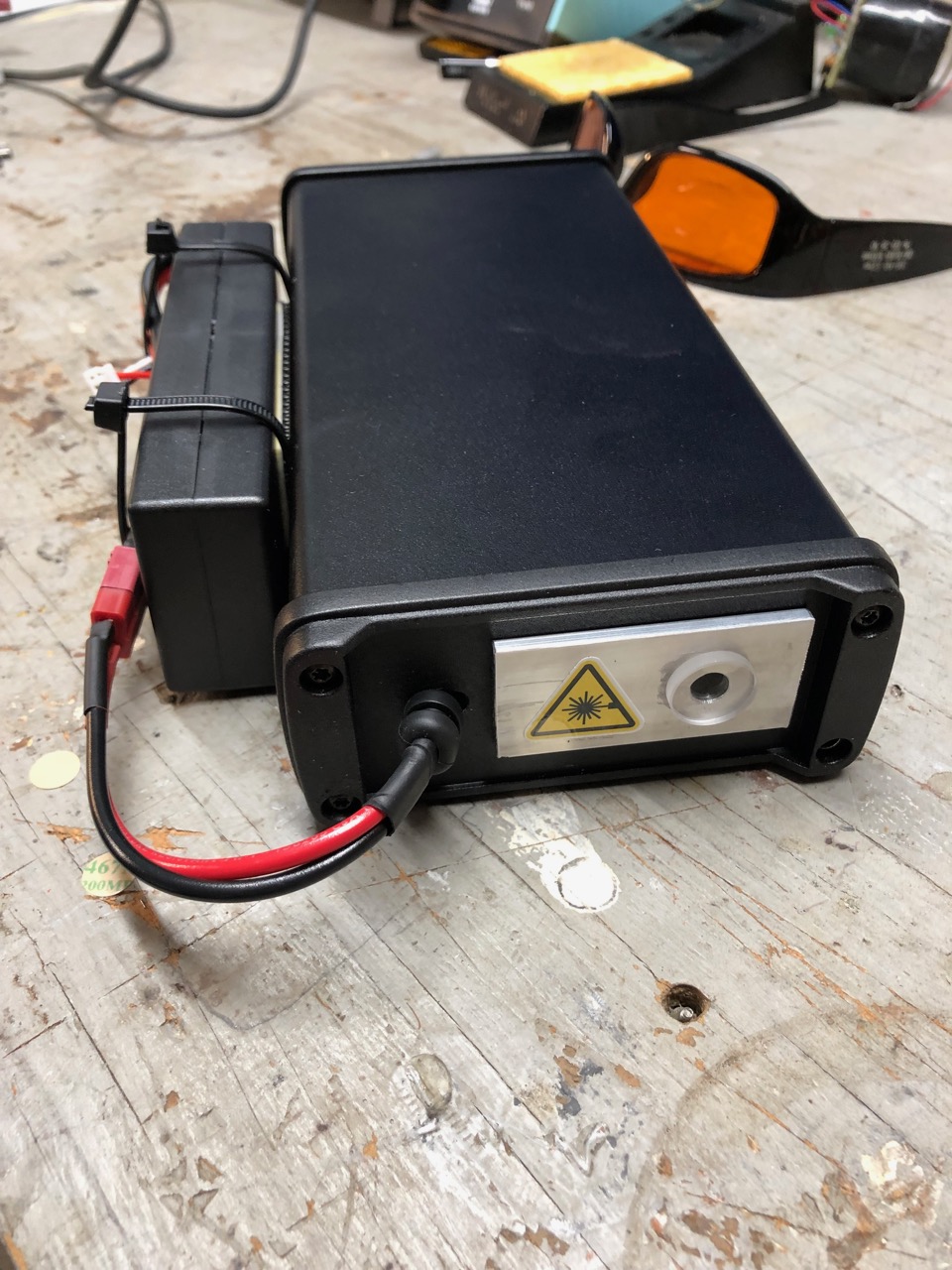
I wanted to see if I could make something with two NUBM44 diodes beam combined and corrected for a better beam profile and decided on a lab format to give me space for optics. I also battery powered it from a large RC car LiPo, so it's portable. I partially succeeded. The NUBM44 is really a horrible diode for beam quality, but if you want photons (and I wanted to see how far I could crank this), it's the easiest ticket in.
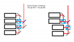
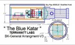
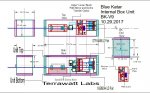
Design
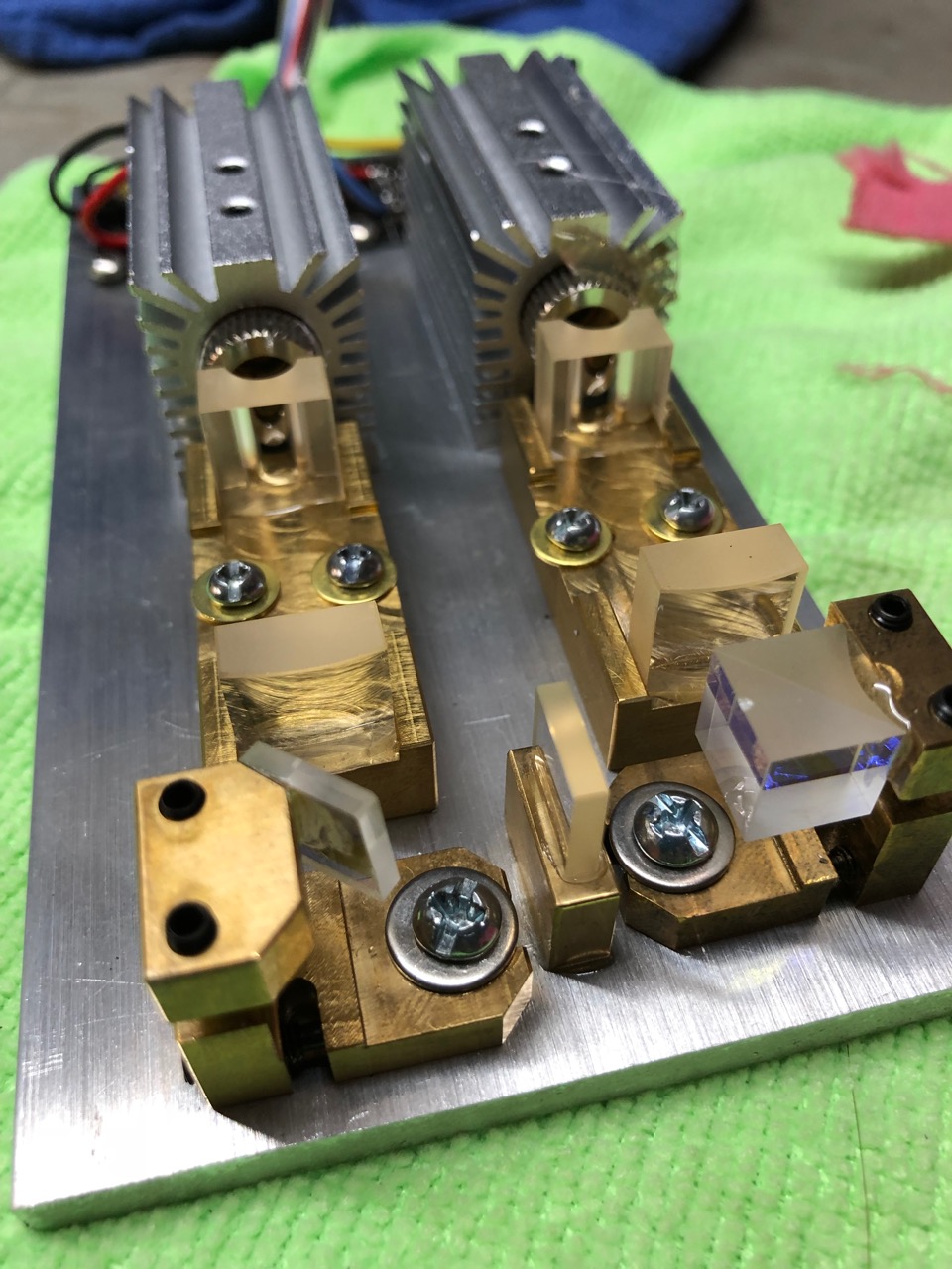
The laser uses two NUMB44-81 445nm diodes from DTR. They are focused to infinity with G2 lenses, pass through dual 6x cylindrical lens pairs to tighten the beam, and are combined with a PBS beam cube. One of the lasers has its polarization rotated with a 90 degree wave plate.

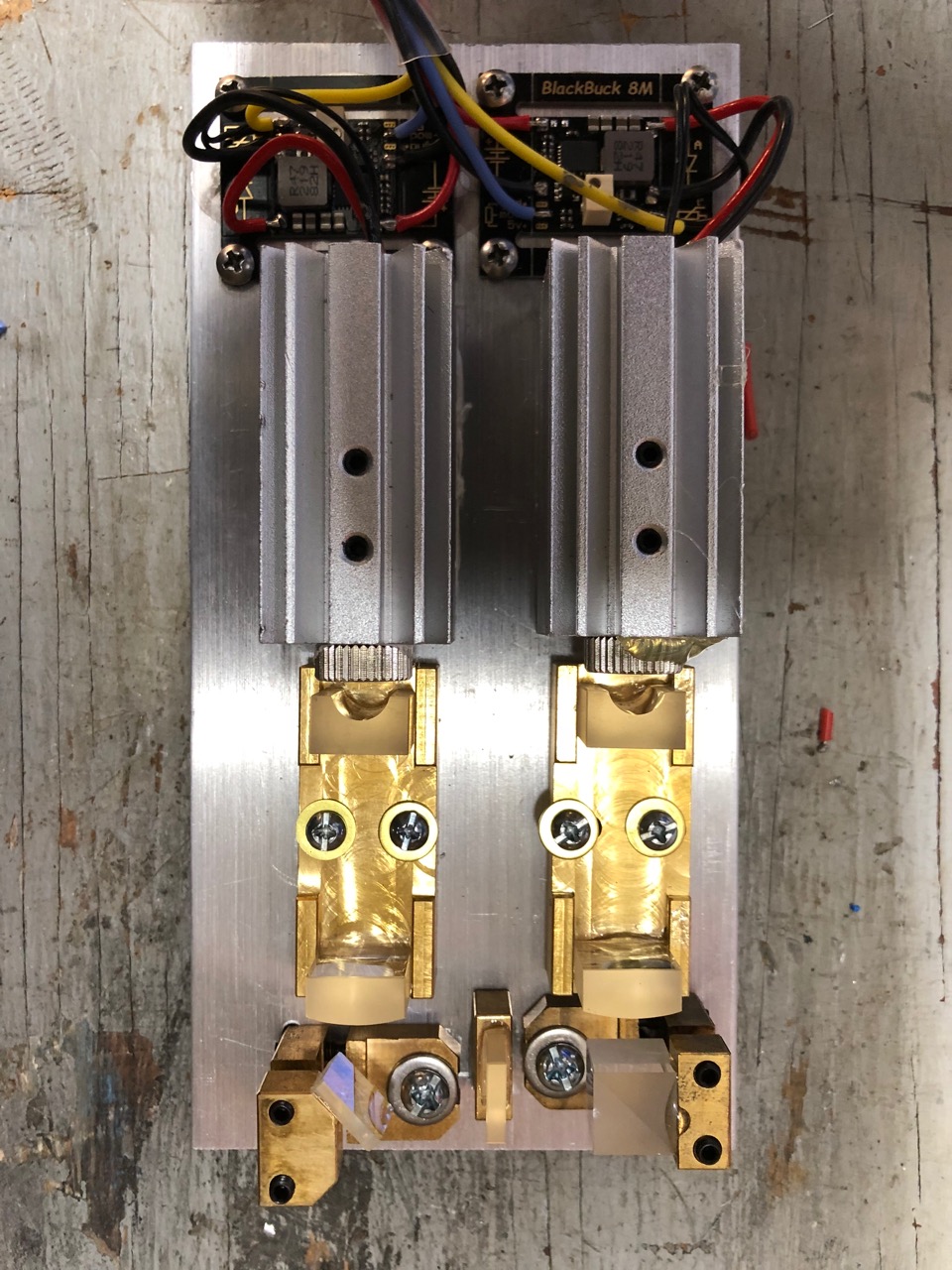
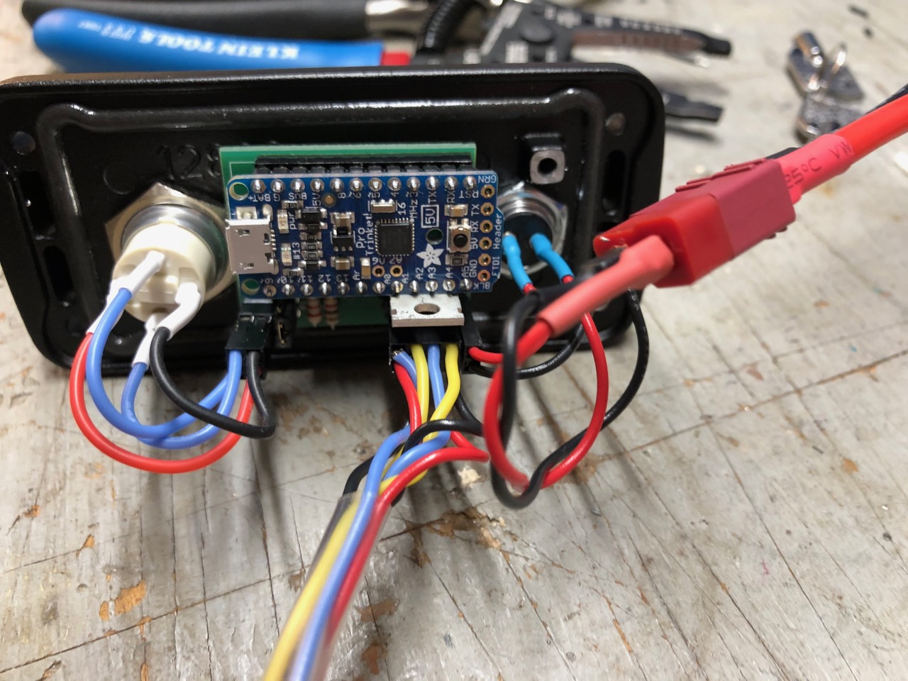
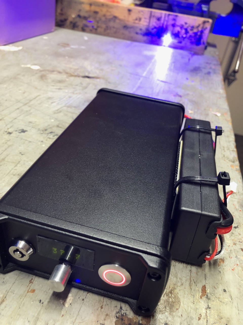
Each laser is coupled to an 8A buck driver preset to 5.5A of max current. The drivers have thermistors on the diodes and are microprocessor controlled via PWM so I can control the power from the front panel. The front panel has an LED display to show power output percentage, a latchable fire button knob for power control, and a key interlock.

Here are some shots of the optics and electronics:


Alignment
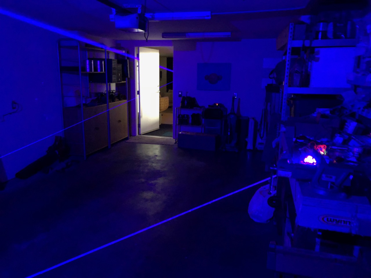
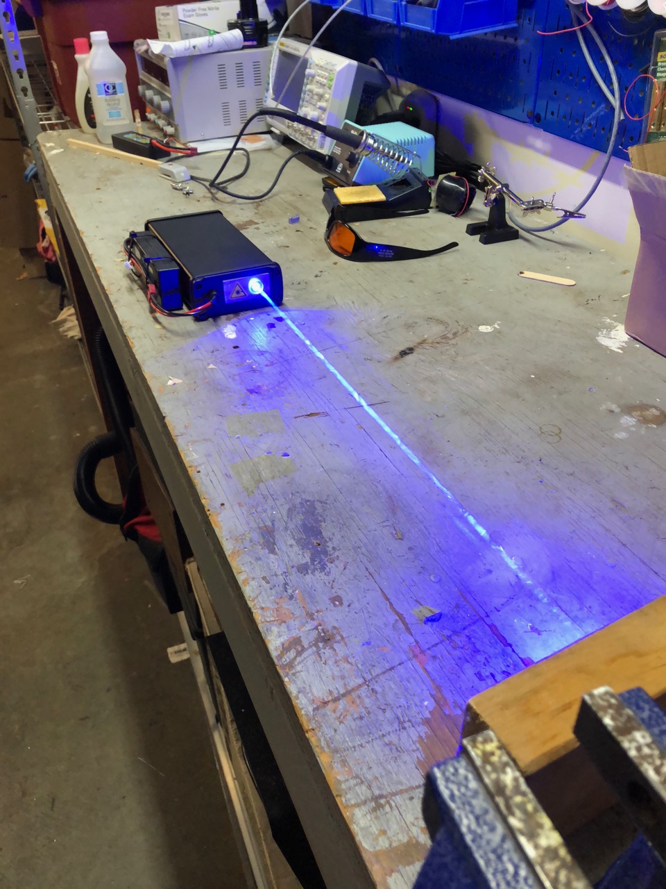
I aligned the beams and focused as close to infinity as I could using an array of mirrors in my garage / basement: about 100' of total travel. When aligned, the spot size was about 4" over 100', for a divergence of about 3.2mrad.


Finished Result
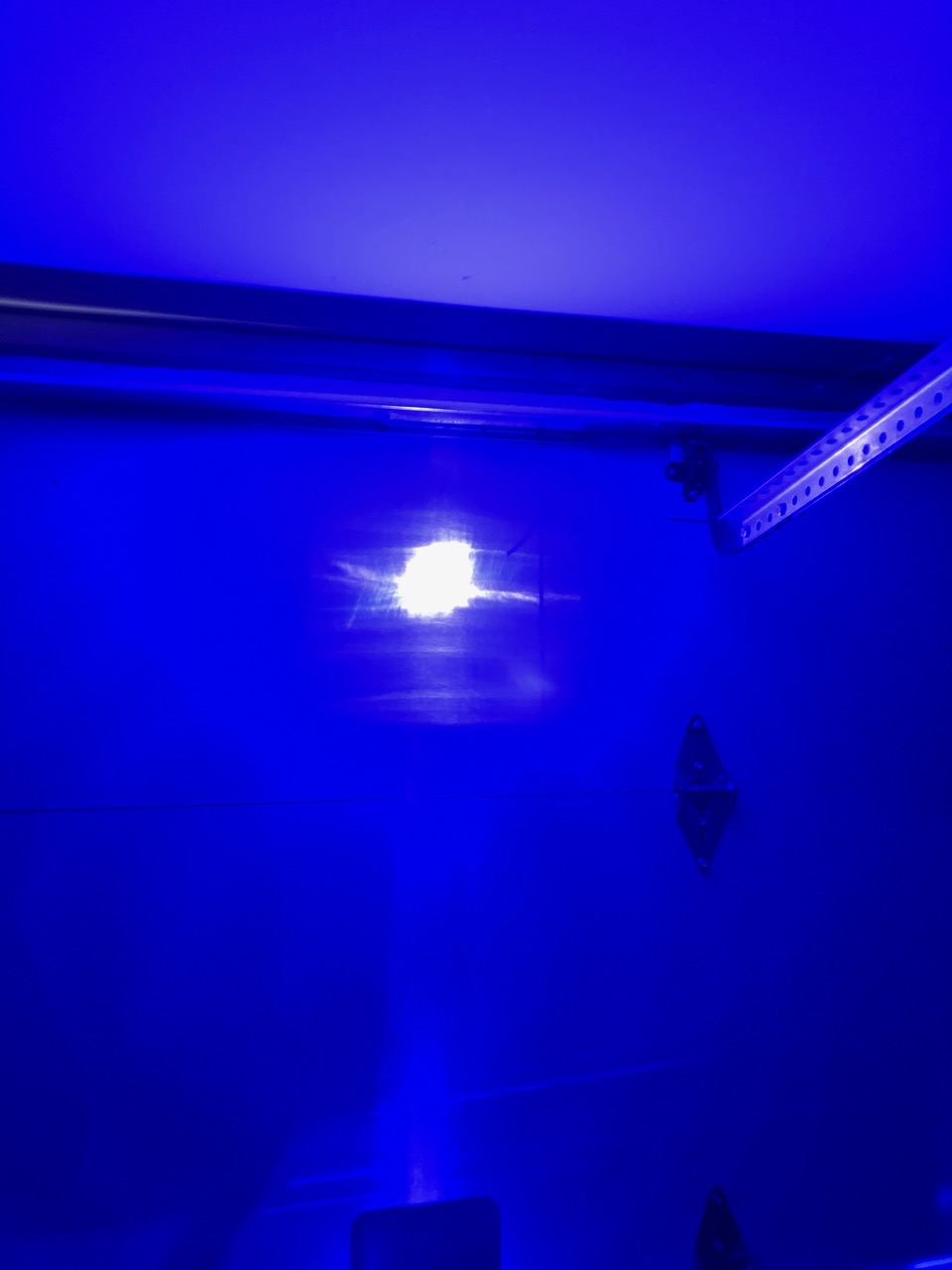
The final laser outputs over 11 watts of light. I've maxed out my Ophir head (+-12v rails).


Next Project
I'm going to refine this for my next project. I'd like to improve the optics to reduce the divergence and possibly integrate a beam expander in reverse to get a narrower beam and higher power density. I'm also going to rev the electronics and programming -- the minimum PWM today for lasing is 10%, which is over 1W and already class IV. I'm going to halve this by shutting down one diode until I need higher power levels.

I'm also going to improve the display and control electronics. The display is pretty dim and I'd like to show temperature of the diodes and amperage. I'm also going to move away from a simple pot to control PWM power and use a digital rotary encoder. That way I can safely start the lasers at zero every time the device is switched on. I also plan to build the battery into the case and provide integrated charging and support for running off mains. Because why not?

But first, my LPM needs a revision before I can measure any improvements here.


Joined
Jun 3, 2007
Messages
2,560
Points
113
Last edited:

diachi

0
Joined
Feb 22, 2008
Messages
9,700
Points
113
Nice build! Very clean! What's the duty cycle like?
 
Joined
Dec 26, 2012
Messages
55
Points
18
I've had no trouble running it for several minutes at a time. More worried about what it's pointed at. The heat sinks aren't very big but they are screwed + thermal compound to a large hunk of aluminum, which is itself screwed to the aluminum case.
 
Joined
Dec 26, 2012
Messages
55
Points
18
Joined
Jul 10, 2015
Messages
9,799
Points
113
Great project brianpe. (y)

Try this, fast axis collimation (FAC). A member responded on a thread I started a few weeks back. Use a single cylindrical lens to collimate the fast axis followed by a longer focal length plano aspherical lens or plano-convex to collimate the beam. I'll check the thread and link it. https://laserpointerforums.com/thre...ry-option-question.103670/page-2#post-1550552

That won't be easy and not sure it would work, the output looks like a line ( - ) because that's how it exits the p/n junction, when using the c-lens pair the diode is rotated so the output looks like this ( l ) as it hits the 1st lens and the narrow axis is the rapidly diverging axis, it diverges rapidly so placement ( distance from the facet ) of a FAC lens would be crucial to make a square beam.....actually it might need a FAC for each axis and we are talking about removing the can which will drastically shorten the diodes lifespan, now maybe a single c-lens could be used on each axis just outside the diode to correct and square the beam, but as the G2's FL is 2.39mm and that still produces a ( l ) that you can see on the concave C-lens when using the pair the thickness of the lenses themselves could becomes an issue when attempting to compete with the G2 and 6X arrangment's results/beam dia.

If it's possible to compete with the G2 and 6X arrangement within a reasonable device length and can be adjusted in such a tiny working space I would love to see it done, but compared to the 6X c-lens pair it looks like the hard way unless the factory were to set the FAC possibly under a longer window can, also remember the narrow axis outruns the wide axis in short order without the G2 primary it all gets big fast.

Here's some pics that I took showing what I mean.

This is the p/n seen through the facet

1kxnubm06a.JPG

Here's the wide axis that diverges slowly.

nubm06raw4.JPG

Here's the narrow axis that diverges rapidly, see how it's hitting the table below, it hits the table in less distance than the block is high.
What exited the facet as a long horizontal line wider than tall is now a fat vertical line much taller than wide.
nubm06rawtabletopb2.jpg
 
Last edited:
Joined
Jun 3, 2007
Messages
2,560
Points
113
Great project brianpe. (y)


That won't be easy and not sure it would work, the output looks like a line ( - ) because that's how it exits the p/n junction, when using the c-lens pair the diode is rotated so the output looks like this ( l ) as it hits the 1st lens and the narrow axis is the rapidly diverging axis, it diverges rapidly so placement ( distance from the facet ) of a FAC lens would be crucial to make a square beam.....actually it might need a FAC for each axis and we are talking about removing the can which will drastically shorten the diodes lifespan, now maybe a single c-lens could be used on each axis just outside the diode to correct and square the beam, but as the G2's FL is 2.39mm and that still produces a ( l ) that you can see on the concave C-lens when using the pair the thickness of the lenses themselves could becomes an issue when attempting to compete with the G2 and 6X arrangment's results/beam dia.

If it's possible to compete with the G2 and 6X arrangement within a reasonable device length and can be adjusted in such a tiny working space I would love to see it done, but compared to the 6X c-lens pair it looks like the hard way unless the factory were to set the FAC possibly under a longer window can, also remember the narrow axis outruns the wide axis in short order without the G2 primary.

Here's some pics that I took showing what I mean.

This is the p/n seen through the facet

View attachment 62469

Here's the wide axis that diverges slowly.

View attachment 62470

Here's the narrow axis that diverges rapidly, see how it's hitting the table below, it hits the table in less distance than the block is high.
What exited the facet as a long horizontal line wider than tall is now a fat vertical line much taller than wide.
View attachment 62472
It's worth experimenting.
There's just one fast axis. Placing a cylindrical lens oriented correctly close to the diode can tames it. Then placing a plano-convex or plano-aspherical lens a distance equal to the focal length will collimate the beam reducing the divergence. Using two cylindrical lenses are necessary to circularize the beam. That's an option, but his goal seems to be decreasing the divergence yo dump more energy into a given area.

PS. Why limit yourself to using G type lenses? Use lenses with wider diameters.
 
Last edited:
Joined
Jul 10, 2015
Messages
9,799
Points
113
It's worth experimenting.
There's just one fast axis. Placing a cylindrical lens oriented correctly close to the diode can tames it. Then placing a plano-convex or plano-aspherical lens a distance equal to the focal length will collimate the beam reducing the divergence. Using two cylindrical lenses are necessary to circularize the beam. That's an option, but his goal seems to be decreasing the divergence yo dump more energy into a given area.

PS. Why limit yourself to using G type lenses? Use lenses with wider diameters.

The cylindrical pair is also a single axis beam expander that reduces divergence, if you use a single c-lens and a plano-convex as you say it may be possible to get a tighter starting beam dia. but the divergence will suffer.

You can trade beam dia. and focal length for the distance between lenses/device length and adjust the dia. of your far field spot, but you can't get something for nothing.
 
Last edited:
Joined
Jun 3, 2007
Messages
2,560
Points
113
The cylindrical pair is also a single axis beam expander that reduces divergence, if you use a single c-lens and a plano-convex as you say it may be possible to get a tighter starting beam dia. but the divergence will suffer.

You can trade beam dia. and focal length for the distance between lenses/device length and adjust the dia. of your far field spot, but you can't get something for nothing.
True, but that might be all he needs to accomplish his goal. Maybe he'll see these two posts and elaborate
 

GSS

0
Joined
Apr 28, 2015
Messages
5,053
Points
113
I can picture RedCowBoy jumping up from a deep sleep sensing a dual NUM44 at 5.5A with CORRECTIVE!! optic's build when Brian posted this:ROFLMAO::giggle:
 
Joined
Jul 10, 2015
Messages
9,799
Points
113
I can picture RedCowBoy jumping up from a deep sleep sensing a dual NUM44 at 5.5A with CORRECTIVE!! optic's build when Brian posted this:ROFLMAO::giggle:

I have corrected and converged 3 x 44's and I still want a lot more, I was thinking about a bunch of 405's but I hear that single mode 450's may be coming in the 1.5w+ range, single mode diodes would make knife edging and stacking possible, I still think about fiber combining visible diodes but it looks expensive, I think if we get these new single mode blues that will be fun, depending on what they cost of course.

Also I understand setting the driver limit at 5.5a to leave headroom but I would not push 44's past 5.0a for any length of time without active cooling as the heat fade if palpable as waste heat bottlenecks, with active cooling the diodes can be more efficient, I have many TEC pads as well as lots of fans and finned sinks but have not done much with them yet.
 
Last edited:
Joined
Sep 20, 2013
Messages
17,253
Points
113
Very nice build, Brian. It looks very clean and well assembled. Congrats on this combined laser. ;)
 

Benm

0
Joined
Aug 16, 2007
Messages
7,896
Points
113
Nice build - not to sure you could call it portable but at least luggable or unreliant off mains power.

The arduino control over the whole system is nice. Given how many anlog inputs that has, you can monitor not only the laser temperature, but also things like their actual current and voltage, as well as battery parameters. There are more analog inputs available than indicated on the typical board, you can have many as at 8 (or even 10) available on the chip, so you could monitor 3 parameters for each laser and 2 for each cell if you wanted to :)
 
Joined
Feb 25, 2010
Messages
1,643
Points
113
NICE !!!!! VERY NICE....Somewhat similar to my " Purple pHAZE " project......with the Box construction and powering with an RC LiPo !!!.....and combining two LD's. Many VERY nice features your build has....I will probably,....er…." borrow" some of them in a future build of my own !!! Thanx !!!!!!! A few suggestions...

1) Do NOT put the LiPo cell within the box interior. Lipo's are peculiar....and have been known to go up in flames. I went that route...putting the LiPo in the Box...and I open the box up, take the Lipo out to charge !!!....JUST cause...I am AR !!! I would keep the LiPo outside the box on future iterations. Outboard LiPo looks a little more " Steampunk....not as streamlined.....but....it is more functional that way.

2) ADD an additional Plano Concave lens in the optical train....see my drawing attached of the Blue Katar concept !! Back to back Plano Concave lenses. I HAVE done this...and achieved ….IIRC....about 1.044 mRad with the 044 beam.....you might see a substantial reduction of divergence with this simple addition. I gotta find the post....but....I believe I was testing the Opt Laser Cylindrical lenses. Looks like you have a slight length of channel to set the second optic on....maybe place a correct height spacer to support the second lens completely...….OR order another set of Brass holders....and four (4) Plano Concave lenses....and centre all the lens doublet within the channel length ??

3) Just an observation.....Although a solid 15mm slab of CU is a hell of a heat sink ( Purple pHAZE attribute)....it is way overkill....for the typical operations.....one thing it does accomplish....STRAIN ON YOUR WRIST !!! HAHAHA.....Add a temp sensor with readout....that well let you know how far ya can push it !! I think the current heat sink arrangement is just fine !!

I threw in the Blue Katar reference....as a possible path to a four (4) High Power Diode design. The only way I see to get a...Beam on Beam on Beam on Beam configuration....is to do the attached concept.
Two LD @ 450nm and two LD @ 465nm. I have the special Dichro. I have NOT done any experiments....THAT will be a 2019 project.

Thanx for sharing !! THIS is NOT the typical build.....But I really like it !!! For....I think....we will have more builds using the " Box Construction " format. Such a platform gives us room to do our optics....and add on function monitoring !!!...This Hobby is evolving.....More and more power....more advanced optics.....You ALL know where we are going !!! Crap....I need to do more research on DiLithium Crystals !!!
...or maybe.....https://arstechnica.com/science/201...n-graphene-an-intriguing-battery-possibility/
We will indeed..." Ride on the Coat Tails " of Electric Car technology.....Good...THAT WORKS !!

CDBEAM
 

Attachments

  • Beam on Beam Blue.png
    Beam on Beam Blue.png
    18.6 KB · Views: 12
  • BK-General Arrangment-V3.JPG
    BK-General Arrangment-V3.JPG
    302.7 KB · Views: 12
  • BK-V9.JPG
    BK-V9.JPG
    150.7 KB · Views: 11
Last edited:
Joined
Dec 26, 2012
Messages
55
Points
18
NICE !!!!! VERY NICE....Somewhat similar to my " Purple pHAZE " project......with the Box construction and powering with an RC LiPo !!!.....and combining two LD's. Many VERY nice features your build has....I will probably,....er…." borrow" some of them in a future build of my own !!! Thanx !!!!!!! A few suggestions...

1) Do NOT put the LiPo cell within the box interior. Lipo's are peculiar....and have been known to go up in flames. I went that route...putting the LiPo in the Box...and I open the box up, take the Lipo out to charge !!!....JUST cause...I am AR !!! I would keep the LiPo outside the box on future iterations. Outboard LiPo looks a little more " Steampunk....not as streamlined.....but....it is more functional that way.

2) ADD an additional Plano Concave lens in the optical train....see my drawing attached of the Blue Katar concept !! Back to back Plano Concave lenses. I HAVE done this...and achieved ….IIRC....about 1.044 mRad with the 044 beam.....you might see a substantial reduction of divergence with this simple addition. I gotta find the post....but....I believe I was testing the Opt Laser Cylindrical lenses. Looks like you have a slight length of channel to set the second optic on....maybe place a correct height spacer to support the second lens completely...….OR order another set of Brass holders....and four (4) Plano Concave lenses....and centre all the lens doublet within the channel length ??

3) Just an observation.....Although a solid 15mm slab of CU is a hell of a heat sink ( Purple pHAZE attribute)....it is way overkill....for the typical operations.....one thing it does accomplish....STRAIN ON YOUR WRIST !!! HAHAHA.....Add a temp sensor with readout....that well let you know how far ya can push it !! I think the current heat sink arrangement is just fine !!

I threw in the Blue Katar reference....as a possible path to a four (4) High Power Diode design. The only way I see to get a...Beam on Beam on Beam on Beam configuration....is to do the attached concept.
Two LD @ 450nm and two LD @ 465nm. I have the special Dichro. I have NOT done any experiments....THAT will be a 2019 project.

Thanx for sharing !! THIS is NOT the typical build.....But I really like it !!! For....I think....we will have more builds using the " Box Construction " format. Such a platform gives us room to do our optics....and add on function monitoring !!!...This Hobby is evolving.....More and more power....more advanced optics.....You ALL know where we are going !!! Crap....I need to do more research on DiLithium Crystals !!!
...or maybe.....https://arstechnica.com/science/201...n-graphene-an-intriguing-battery-possibility/
We will indeed..." Ride on the Coat Tails " of Electric Car technology.....Good...THAT WORKS !!

CDBEAM
Fantastic, thanks for all the info cdbeam777. I actually did have analog inputs monitoring the temperature thermistors. My PC board may have been wrong or I had the Arduino configured incorrectly, because I got no power output. That's one of the things I plan to debug in v2. Screen was too small anyway. Thanks a ton for the optics ideas, and the warning about the LiPo.


Top