- Joined
- Jul 10, 2015
- Messages
- 13,115
- Points
- 113
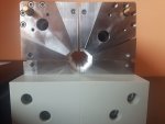
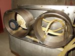
I would bet the mirrors are enclosed in the end structures.
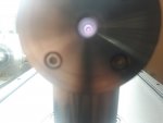
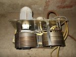
I would like to see the pump diodes from the output end also.
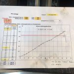
With 4 strings each driven at 42v and 50a that's 8000w input power, maybe 4000 out of the pumps and what ???? 500-1000w out of the rod ?
If 7000w of waste heat it no doubt needs a chiller, I wonder what the normal operating temp is ?
You could power just 2 strings, one on each side at reduced power with a deionized water loop, but I would monitor the water temp, and get some proper eye protection first !
Last edited: