Jufran88
0
- Joined
- Feb 9, 2011
- Messages
- 578
- Points
- 0
So, after designing a LMS1587 based linear driver rhd introduced me to the MIC29312 IC. I already sent my LMS1587 design to the board house and I couldn't get this in because it passed the deadline for submission. There is plenty of time before the next deadline so I could still tweak the design if needed.
data sheet: *here*
It's an ultra low drop out linear regulator with better specs than the LMS1587 and includes an enable switch that can be used as a safety switch. If not then it can be soldered with V+.
Specs:
Regulator Topology: Positive Adjustable
Voltage Output: 1.24 V ~ 15 V
Voltage Input: 2.3 V ~ 16 V
Voltage Dropout (Typical): 0.6V @ 3A
Number of Regulators: 1
Current Output: 3A
Current Limit (Min): 3A
Operating Temperature: 0°C ~ 125°C
Mounting Type: Surface Mount
Package/Case: TO-263-6, D²Pak (5 leads + Tab), TO-263BA
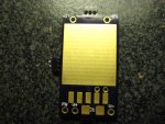
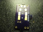
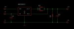
Schematic:

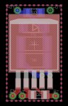
Board:

* It might be hard to see all the connections because some parts are connected to the ground plane.
comments, questions, concerns are welcomed!
data sheet: *here*
It's an ultra low drop out linear regulator with better specs than the LMS1587 and includes an enable switch that can be used as a safety switch. If not then it can be soldered with V+.
Specs:
Regulator Topology: Positive Adjustable
Voltage Output: 1.24 V ~ 15 V
Voltage Input: 2.3 V ~ 16 V
Voltage Dropout (Typical): 0.6V @ 3A
Number of Regulators: 1
Current Output: 3A
Current Limit (Min): 3A
Operating Temperature: 0°C ~ 125°C
Mounting Type: Surface Mount
Package/Case: TO-263-6, D²Pak (5 leads + Tab), TO-263BA
Schematic:
Board:
* It might be hard to see all the connections because some parts are connected to the ground plane.
comments, questions, concerns are welcomed!


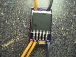
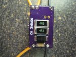
 . It's worth the wait because the boards are very high quality! I could send you a sample when I get the boards just pay me for the shipping costs.