Johnyz
0
- Joined
- Jul 19, 2010
- Messages
- 421
- Points
- 0
So, as I finally managed to find an empty projector (the one we love extracting Nichia LD's out of) (also, thanks, Greg!), I tried to find a driver for the precious Phlatlight PT-54 red LED. Now, since I was intending to use it with a 5V 10A supply, I needed a driver, that needs less voltage for itself (DDL needs additional 3V+ above the diode forward voltage). I also needed the driver to handle a high current (set it to about 8 amps and something, to be safe).
CandlePowerForums came with a nice thread.:
Super-Simple Power MOSFET Linear Current Regulator
Oh, and by the way,

This work is licensed under a Creative Commons Attribution-Noncommercial-Share Alike 3.0 License.
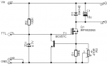
Image from the original thread:

If you don't need the PWM in, just leave the part with the blue/grey background out, and it will work without it.
For my red beast, I just replaced the parts with some more power ones: the megaohm resistor for a 2W one, the current set resistor for three 0,22 ohms 20W (so we get 0,073 ohms and 60W) and the transistor for BU508A. The MOSFET can be also replaced for a IRF3205, just to be safe.
Now, where my idea lies, if we could add a capacitor or two, and replacing the resistors with one that limits the current, to, say, 1.5A and a multi turn pot we all know from DDL drivers, we could be driving laser diodes, am I right?
The problem is, that power is being pushed through the current set resistor (and through our pot), so, unless we use just one precalculated resistor, we couldn't probably drive a 445 LD at its maximum amperage, but I still think this would be nice to drive a LPC or some similar LD's from a single Li-Ion.
DISCLAIMER: I do not take credit for the circuit, I only came up with ideas that are written under the picture. I also do not take responsibility if you blow any electronic parts, or injure somebody! EVERYTHING DONE AT YOUR OWN RISK.
CandlePowerForums came with a nice thread.:
Super-Simple Power MOSFET Linear Current Regulator
Oh, and by the way,
This work is licensed under a Creative Commons Attribution-Noncommercial-Share Alike 3.0 License.
Image from the original thread:
If you don't need the PWM in, just leave the part with the blue/grey background out, and it will work without it.
For my red beast, I just replaced the parts with some more power ones: the megaohm resistor for a 2W one, the current set resistor for three 0,22 ohms 20W (so we get 0,073 ohms and 60W) and the transistor for BU508A. The MOSFET can be also replaced for a IRF3205, just to be safe.
Now, where my idea lies, if we could add a capacitor or two, and replacing the resistors with one that limits the current, to, say, 1.5A and a multi turn pot we all know from DDL drivers, we could be driving laser diodes, am I right?
The problem is, that power is being pushed through the current set resistor (and through our pot), so, unless we use just one precalculated resistor, we couldn't probably drive a 445 LD at its maximum amperage, but I still think this would be nice to drive a LPC or some similar LD's from a single Li-Ion.
DISCLAIMER: I do not take credit for the circuit, I only came up with ideas that are written under the picture. I also do not take responsibility if you blow any electronic parts, or injure somebody! EVERYTHING DONE AT YOUR OWN RISK.


")