Welcome to Laser Pointer Forums - discuss green laser pointers, blue laser pointers, and all types of lasers

LPF Donation via Stripe | LPF Donation - Other Methods

Links below open in new window

ArcticMyst Security by Avery

Using a DC/DC converter to power the laser

phenol

0
Joined
Oct 30, 2007
Messages
533
Points
18
it looks like it should be in the sub 0.1 ohm range, depending on peak switching current. and it depends on the load current , in/out voltage, Vsat of transistor, Vf of diode...
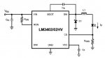
Edit:  driving a dvd LD with this cct off 3 or less volts would require Ipk to be quite high, so you should find a low Vcesat transistor with high gain in the ampere range of Ic, as the output drive capability of the boost chip is only 3-5mA.


woop

0
Joined
Nov 9, 2007
Messages
342
Points
0
phenol said:
LM311 is a comparator. Try LM358 instead, or at best - one with input and output common-mode range including supply rails.

what did you mean input and output common-mode range......

and will this work? it is just a semi-educated guess
 

Attachments

  • will_this_work.JPG
    will_this_work.JPG
    13.2 KB · Views: 779

phenol

0
Joined
Oct 30, 2007
Messages
533
Points
18
no... its output (open collector) will be very close to Vcc if V+>V- This is a comparator and its output toggles between 0 and 5 volts. If you want a to sense the voltage differential across a shunt /or anything/, you will need a summing op-amp, for instance the one in the circuit fragment shown here. Its output is exactly equal to the voltage across the 1.8-ohm shunt. How it works:
The Vout of the amp when applying signal on the non-inverting pin (taking in account all resistor networks) is ((Rf/R1)+1)*(Vhi /2)=Vhi. Now for Vout in inverting mode with Vlo on the input: Vout=-(Rf/R1)Vlo =- Vlo. since both Vhi and Vlo are applied at the same time, Vout is equal to their sum: Vout=-Vlo+Vhi=Vhi-Vlo, which is in fact the voltage drop across Rsense. The reason why i would prefer op amps that can behave linearly with input voltages within supply rails and swing their outputs within supply rails is partially evident in the example above: for a very small drop across Rsense Vout has to be very close to Vdd. If the op amp has a bipolar output stage, it wont work in this examlpe for very small Vrsense, unless its power supply is higher than Vh.
Furthermore, playing with the resistor values, you could also amplify the differential by a given amount: Vout=k(Vhi-Vlo)
Here you can see how i use this in a current source:
http://www.laserpointerforums.com/forums/YaBB.pl?num=1193741215/30
 

Attachments

  • vd.JPG
    vd.JPG
    18.5 KB · Views: 395

woop

0
Joined
Nov 9, 2007
Messages
342
Points
0
ahh. ok. thanks for the info. i should really learn how to use opamps. i suppose i will learn in my electronics engineering course i am starting this year.
anyway. i was going to try the lm158 you suggested. simply because i can get it around the corner.
i found a current measurement schematic in the datasheet. (i love it when they include examples in datasheets)
if i wanted to put the shunt between the load and ground i would use the non-inverting input right? so would the following schematic work for that situation? it would simplify things a bit
 

Attachments

  • lm158_.JPG
    lm158_.JPG
    17.6 KB · Views: 824

phenol

0
Joined
Oct 30, 2007
Messages
533
Points
18
yes, it would. LM358 has Vicm ncluding ground (for single power supply), so you could use it to amplify any sense voltage lower than the chip's upper input commont mode limit for the given supply voltage.
 

IgorT

0
Joined
Oct 24, 2007
Messages
4,177
Points
0
Well, i think i finally found the right solution for my problems..

The only reason i was obsessing with step up converters was, because i wanted all my lasers to fit into this nice little enclosure i found.
The enclosure is only 74.5 x 44.5 x 18 mm and has a very attractive shape, and a button built in. It's meant for garage door openers or similiar remotes.

The problem is, it is designed for a small 12V battery, that has no capacity to speak of, but it's still big enough for two AAA batteries, some circuitry and the AixiZ laser module.


Now that i finally managed to find small Li-Po batteries of the same size as an AAA (UltraFire 10400 - 3.6V / 500mAh), i could use this enclosure for a burner with a normal 317 regulator. Unfortunatelly this is not the solution for Blue Rays, if i want them current regulated..

Luckily i managed to order some current regulated buck converters from National Semiconductor - the LM3402.. The circuit is VERY simple and requires only a single resistor to set the current. A resistor for limiting the max. current and a precision trimmer would be perfect for driving BlueRays from only two LiPo cells, and at a very high efficiency. The 3402 works down to 6V input voltage, which makes it perfect for this application.

If it works well, i might even use it for the burners. The efficiency would be at least double, compared to the 317 circuit.


Here's the circuit diagram, if anyone is interested...
 

Attachments

  • LM3402_buck_circuit.jpg
    LM3402_buck_circuit.jpg
    14.9 KB · Views: 8,160
Joined
Feb 13, 2008
Messages
62
Points
0
Mouser.com has Zetex LED drivers for sale, most of them you can buy in low quantities. Your right, Coil Craft is where I got inductors for experimenting with DC-DC converters. I bought one of their designers kits for projects and it came with many different values. I used the converter datasheet to pick a kit that had the most applicable inductors. It cost a bit but know I don't need to worry about having the right value :)
 

woop

0
Joined
Nov 9, 2007
Messages
342
Points
0
thanks phenol, i was going to use it for another project as well.

the lm3410 looks alright. its up to 2.4A and can be used in sepic configuaration, which lets you use a input that is higher or lower than the output, like a single lithium battery. and its pretty simple
 

IgorT

0
Joined
Oct 24, 2007
Messages
4,177
Points
0
woop said:
thanks phenol, i was going to use it for another project as well.

the lm3410 looks alright. its up to 2.4A and can be used in sepic configuaration, which lets you use a input that is higher or lower than the output, like a single lithium battery. and its pretty simple

Are you sure it can have a lower output, than the input? I just checked it out and it says Output range: Vin to 24V

Need to study the datasheet.. Could be usefull anyway..


EDIT: You're right. It can be converted into a SEPIC converter but it needs two inductors for this, right?

Looks interesting. Thanks!
 

woop

0
Joined
Nov 9, 2007
Messages
342
Points
0
yeah sepec is cool. and any design which will work with higher or lower than output input voltages will require 2 inductors.
so it should be about 80% efficient with a burner and a single li-po.
i wonder how you work out the inductor values for that design
 

IgorT

0
Joined
Oct 24, 2007
Messages
4,177
Points
0
woop said:
yeah sepec is cool. and any design which will work with higher or lower than output input voltages will require 2 inductors.
so it should be about 80% efficient with a burner and a single li-po.
i wonder how you work out the inductor values for that design

Well, after looking at the datasheet i ordered 4x LM3410 samples as well..

The datasheet recommends two inductors of 4.7uH, capable of 3A for a sepic configuration. In that circuit it is driving a LED with 300mA at 3.8V, so the same values might work for a LD.. What do you think?


Unfortunatelly CoilCraft just denied my samples request, since they checked out my company and believe, i don't fulfill their expectations as a high volume manufacturer... On the other hand, my web page is in Slovenian language, so they don't understand, what it is, that we do.. I did my best to explain to them, and seriously hope, they reconsider, or i might end up paying more for the shipping than the inductors.


Anyway, i think this configuration might work without any modification:
 

Attachments

  • LM3410_SEPIC.jpg
    LM3410_SEPIC.jpg
    20.5 KB · Views: 3,336

phenol

0
Joined
Oct 30, 2007
Messages
533
Points
18
coilcraft put my order on hold with the same set of arguments. i doubt they'd bother to read my retort, so i better start winding inductors.
has national confirmed your order yet?

i tried a sepic configuration with MC34063 as per the example above and it did work, the efficiency however is not worth mentioning. i guess i should play a bit more with inductor values
 

chimo

0
Joined
Jun 20, 2007
Messages
650
Points
0
Inductor selection always seems like a black art. It takes a lot of trial and error. Seemingly similarly spec'd inductors from different manufacturers behave differently. Remember to keep the leads very short from the switcher chip when running tests.

phenol said:
coilcraft put my order on hold with the same set of arguments. i doubt they'd bother to read my retort, so i better start winding inductors.
has national confirmed your order yet?

i tried a sepic configuration with MC34063 as per the example above and it did work, the efficiency however is not worth mentioning. i guess i should play a bit more with inductor values
 

phenol

0
Joined
Oct 30, 2007
Messages
533
Points
18
at low switching currents most inductors seemed to perform equally well. once the peak switching current reached a few amperes, things changed drastically from one core to another
 

IgorT

0
Joined
Oct 24, 2007
Messages
4,177
Points
0
phenol said:
coilcraft put my order on hold with the same set of arguments. i doubt they'd bother to read my retort, so i better start winding inductors.
has national confirmed your order yet?
Yeah, that sucks.. I really hope they reconsider.. National on the other hand confirmed the shipment of three different samples so far, 4 each. The LM3402MR, LM3410XSD and LM3410YSD (different frequency).

Once i gave them my company's email, they now ship samples for free. But certain ICs are not available as samples, and they offer similiar ones, which i checked out, but weren't any good...


phenol said:
i tried a sepic configuration with MC34063 as per the example above and it did work, the efficiency however is not worth mentioning. i guess i should play a bit more with inductor values
I was calculating the inductor values for the 3402, using those formulas in the datasheet, and the ones i have ordered should be perfect.. Larger ones could make for a smaller ripple and can provide more current with some ICs..

But i had very bad luck winding my own inductors.. My efficiency was 60% and i couldn't even get close to what those MAX boost ICs should be capable of.

I have an order of various inductors from Conrad waiting for me. They are very cheap - 0.65 Eur each.. They match all the ratings, and i really hope they get the boost circuits working properly... I'm gonna try different ones and see what happens...


Anyway, the 3410 circuit suggests using two 4.7uH coils, for driving that single LED at 350mA.. I have some 10uH with the same current rating and DC resistance, so i'm gonna try those, once i get the chips. If they should not work, i'm gonna order the exact part number and try with that..

But for the 3402, the circuit most suitable is meant to work from 24V... Need to do more calculations, to figure out the best values..


BTW, what kind of capacitors are you using? It's possible, that i lost some efficiency, due to electrolytes in my two MAX circuits.. Should have used tantalums.. Thanks to you, i found a bunch of low ESR tantalums inside those old DVD writers, all the values i need for free.. Otherwise, they are very expensive..
 

woop

0
Joined
Nov 9, 2007
Messages
342
Points
0
I have had a bit more luck in ordering samples than you guys. i think i told coilcraft i was a student. anyway i got 6 of the 4.7uH ones and 2 100uH inductors on the way
and i got national to send some samples of the LM3410 but i had to pay shipping

so you guys have inductance meters or are you just winging it to wind your own inductors?


Top