

- Joined
- Sep 20, 2008
- Messages
- 17,622
- Points
- 113
Sorry, got a question for you since i'm very new to PCB design.
When looking at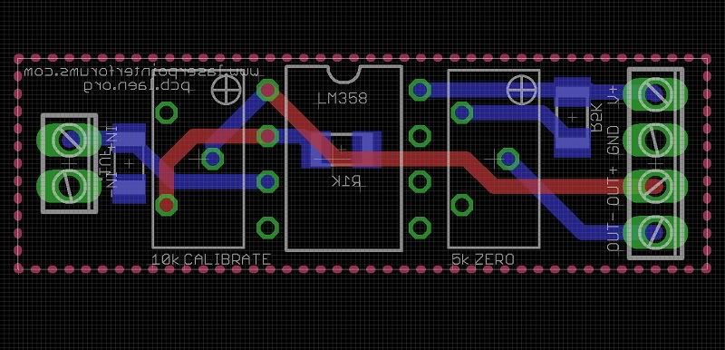
Apart from the VIAs and the 2 red traces, is that really all the copper you have on the top side of your board? Is there still copper everywhere else on the top layer that is simply not connected to your traces?
Also, isn't it best to make use of copper plates as much as possible? I would assume just using traces would cause more noise? Especially regarding power and ground. When looking at PCB design files on this site generally all I see are just traces and not plates... why is that?
Anyone else care to chime in when its best to use a copper plate versus a trace?
What you are referring to are Ground Planes...
It is always a good idea to use ground planes
when dealing with extreme low level signals and
High gain amplifiers...
This circuit is not using extremely low level signals
and the amplifier has a marginal level of gain.
It would not hurt to put ground planes but the circuit
is simple enough to not really require it..
From the pics of the PCB in the 1st post it is obvious
that the PCB design IS using Ground Planes on both
sides of the PCB...
The reason you can't see them on the 2 sided Artwork
is if they were visible you couldn't see the traces easily...
Jerry
Last edited:


