- Joined
- Jan 14, 2009
- Messages
- 1,452
- Points
- 83
Hey ,
This has been a ongoing project for the past month or so on and off and I have finally reached the point where its working as it should .
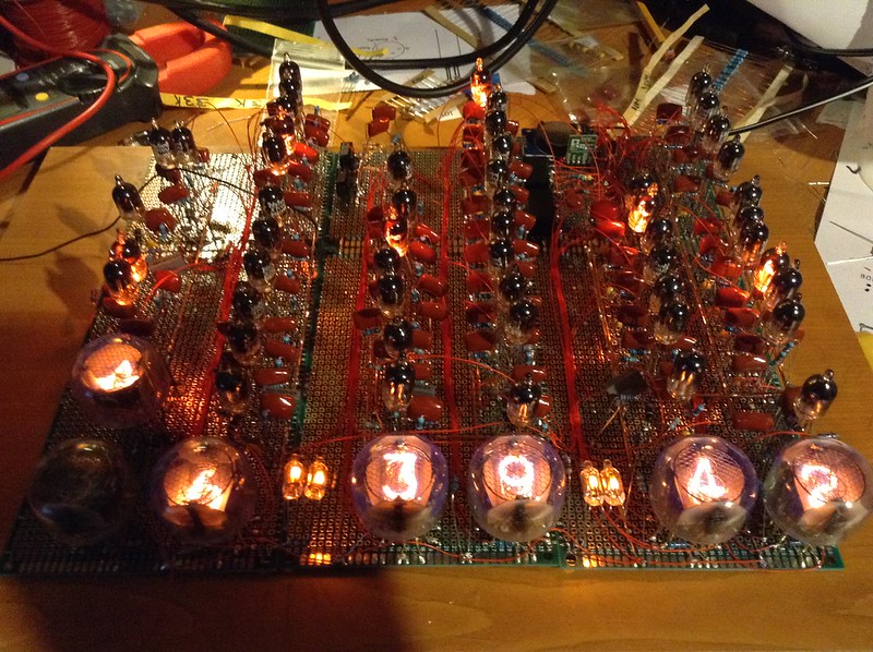
Its a 12 Hour Nixie clock using Z700U trigger tubes and front facing nixie tubes , AM is indicated by a A and PM is indicated by a V ( for now ) , Supply voltage to the board is 415V DC @ 20mA .
Neon indicators between the hours and minuets are polarity switched using a relay to alternate the glow in the tube , Time keeping is done by a RTC module and Arduino to output a 1Hz drive signal that drives a relay and in turn drives the input to the seconds stage .
Its built on prototype board all point to point with a lot of thin coated cable
Not the best picture , hope to have better ones soon along with a video : D
Thanks : D
 008 by TwirlyWhirly555, on Flickr
This has been a ongoing project for the past month or so on and off and I have finally reached the point where its working as it should .
Its a 12 Hour Nixie clock using Z700U trigger tubes and front facing nixie tubes , AM is indicated by a A and PM is indicated by a V ( for now ) , Supply voltage to the board is 415V DC @ 20mA .
Neon indicators between the hours and minuets are polarity switched using a relay to alternate the glow in the tube , Time keeping is done by a RTC module and Arduino to output a 1Hz drive signal that drives a relay and in turn drives the input to the seconds stage .
Its built on prototype board all point to point with a lot of thin coated cable
Not the best picture , hope to have better ones soon along with a video : D
Thanks : D
 008 by TwirlyWhirly555, on Flickr
Last edited:


