Welcome to Laser Pointer Forums - discuss green laser pointers, blue laser pointers, and all types of lasers

Buy Site Supporter Role (remove some ads) | LPF Donations

Links below open in new window

FrozenGate by Avery

What went wrong? 20mw 635nm LD is only 5mw.

Joined
Sep 22, 2010
Messages
1,360
Points
48
A couple months ago I bought a 20mw 635LD in DJNY's GB but never did anything with it until yesterday because I couldn't figure out how to make a case positive build. That all changed when jib mentioned that regulators like the Lm317 or 1117 don't care where the load is they just want to keep 1.25v across their sense resistor at whatever amperage you've set.

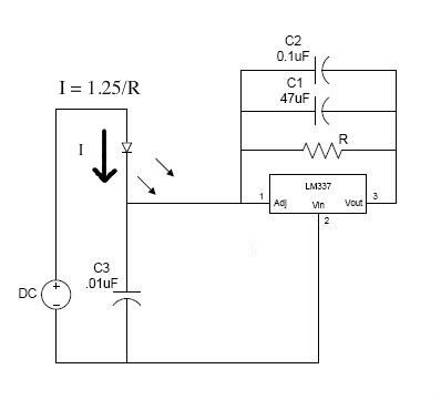
This is the circuit I built after jib's suggestion.
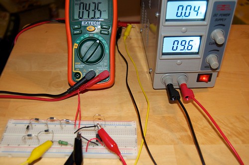

2011-07-04_09-14-43pm by ltkernelpanic, on Flickr

I changed the resistor to 18ohms to give me 71ma and tested it. Everything worked like in the photo above. The LD is supposed to output 20mw at 70ma so in theory it should have worked but when I LPM'd it it only measured 4-5mw.


I had planned on making a detailed build titorial thread on making a case positive build but I'm hesitant in case I screwed something up and damaged my diode. I could post a picture of the build driver tomorrow but it's the same as the one on my breadboard with the exception of the resistor used and a 1N4001 diode added to prevent a reverse polarity.

That all said my question is this. Did I do something to damage my diode or did I just get a dud? I can't see anything wrong with my build so I'm heavily leaning towards an underspec diode. I may pick up another diode since modwerx has the same ones in stock now and build it in a temp labby (my saik heatsink should do the trick ;)) and power it off an identical driver on my breadboard and see if I get 20mw or now.


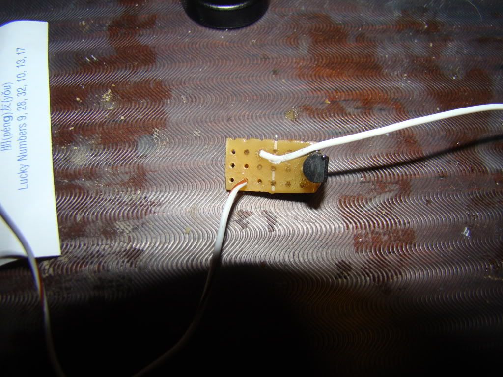
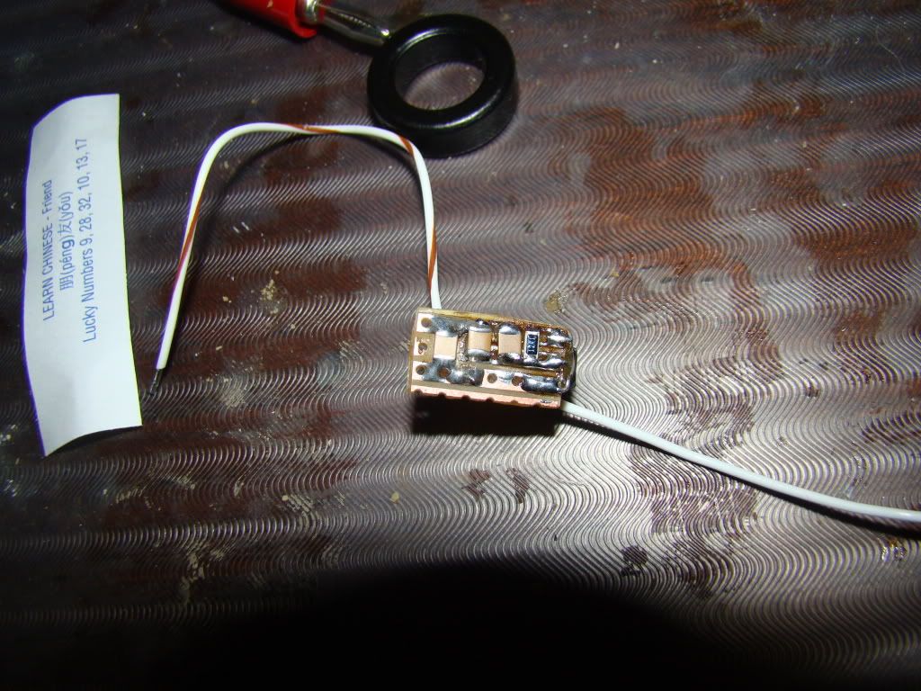
I would like to see the schematic. I dont know if it helps but when I made my own DIY case positive driver I used a LM337L worked great. I hope these pics help.

lowside.jpg


DSC00673.jpg


DSC00674.jpg
 
635nm are IMO the most sensitive diodes i have ever worked with. Especially to heat.

My 7mW 635nm diode will put out 7mW when it Nice and cool and if i dint run it for 3 or 4 hours.

If i use the laser for 2-3minutes it will drop down to 1-2mW. Then once it cools again for a long period of time it will go back up to 7mW.

If you haven't LED it then Try letting it cool down a bit and fire it back up and meter it. You will probebly get a better reading.

I found that Low powered 635nm diode are sensitive with certain drivers you use also. My favorite one is the Aixiz Red one.:) Since they are good with case + builds.

Either you got a Zombie,one that has a higher thresh hold or the diode needs to be cooled down a bit before you test it again.


Iam getting a 20mW 635nm diode on the way to me right now. Should be here in a couple days. Once i get it i also plain on setting it to 70mW:) I will let you know what i get.

Each Diodes are differed but Just for reference i will let you know what i get.:)
 
Last edited:
I've tested it several times and it outputs a steady 4-5mw. I wouldn't be shocked if the diode got damaged in its trip three quarters the way around the world or even here. I don't think i damaged it with heat since it was already pressed and i barely had to tap the pin to make the connection to my pre-tinned wire.


I haven't h ad time to get the pics I took during the build bosted yet and I lack software to make schematics but it's setup this way:

Batt+ (via case and axiz module) -> LD+ -> LD- -> iN4001 (for polarity protection) -> LM317 Vin -> LM317 Vout-> Batt-.

I didn't use any caps because I couldn't figure out how to do it when using the case as one of the "wires" to the LD. I'll try and get a pic or two uploaded shortly.

Just use paint in windows make a rough sketch
 
Hope you get it worked out. I'm lookin forward to seeing a bunch of lower cost 635 builds around here. I'd eventually like to either build or buy a couple of pen builds with a 635. So far I've held off due to the high cost, but it looks like things are changing.
 
Hope you get it worked out. I'm lookin forward to seeing a bunch of lower cost 635 builds around here. I'd eventually like to either build or buy a couple of pen builds with a 635. So far I've held off due to the high cost, but it looks like things are changing.

I built a great 46mw 635nm with batteries for less than $45 I also built a 40mw torch style for about $45. So it can be done, one I used a green laser driver and the other used a LM337 driver.
 
Just use paint in windows make a rough sketch

I don't use that virus known as Windows ;)

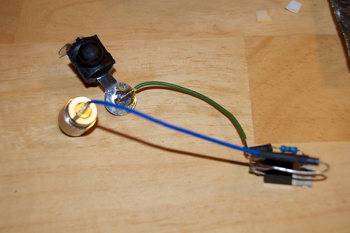
Here's a pic of everything before I put it in the host.


2011-07-09_11-05-21pm by ltkernelpanic, on Flickr

Batt+ comes from the host via the heatsink and Batt- is through the switch.
And before someone says anything there's no way the tab from the LM317 can short against the 1N4001 or resistor once in the in the host. I'm not that inept. :D
 
I don't use that virus known as Windows ;)

Plenty of free software for linux and if you are a mac user I am sure the smallest mom and pop giant corporation has released something in between tricking hippies into thinking they are not an evil corporate giant.
 
Heh sorry that was a joke. I use OS X as my main OS but have several Win XP and 7 machines around the house too. I'll try to draw up a diagram tonight. The mail dude just brought me some new toys. :D I really do appreciate your willingness to help me try to figure out what happened.
 
Heh sorry that was a joke. I use OS X as my main OS but have several Win XP and 7 machines around the house too. I'll try to draw up a diagram tonight. The mail dude just brought me some new toys. :D I really do appreciate your willingness to help me try to figure out what happened.


If you draw it up I can recreate it in the lab and see exactly what the driver is doing.
 
Since I had to fire up VMWare for my laserbee here's a paint diagram. I realized after I finished i probably shouldn't have drawn Batt+ connecting directly to LD+ since it actually connects visa the diode case from the case positive host. When I tested the driver I built on my test load it put out a steady 71ma.

attachment.php
 

Attachments

  • driver.jpg
    driver.jpg
    29.6 KB · Views: 3,394


Back
Top