- Joined
- Feb 5, 2008
- Messages
- 6,252
- Points
- 83
Hello newcomers! Welcome to the laser hobby 
This tutorial will deal with the aspect of housing your laser setup into a portable handheld device. If you require help with the laser setup itself, please view all the sticky threads, tutorials and guides, and if all else fails, send me a Personal Message with your questions and I’ll do my best to get back to you.
Housing a laser into handheld flashlight-alike shell, commonly referred to as “host”, is a lot different than housing it into a project box.
Due to the way flashlight shells are constructed, a lot of work needs to be done, and because of small and usually limited space, you need to be able to solder small parts and work in cramped spaces, have a good spatial awareness regarding the inner workings of the flashlight, and of course, knowledge how to put it all together without breaking anything.
Most commonly, empty shells usually meant for flashlights are used. Some of most common examples include Aurora C6, Ultrafire 501/502b, Guidesman and a lot more others. You’ll notice that these flashlights are made to accept standardized “drop in” modules, like P60. This means that the host allows for modular installation and modification of it’s internal components. Which in turn, means easier job for you.
However, you can't pick up a flashlight simply throw all the components right into it.
Let’s go over few crucial components that make up a flashlight shell and play an integral role in laser assembly.
The Driver Pill
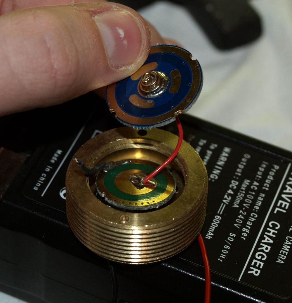
What we refer to as “the driver pill”, is actually a part of the flashlight originally meant to hold the LED emitter and it’s regulation electronics. In most cases it is modular, however if a host already has a pill in it, it means it does not accept standard drop in LED emitter modules. The pill is fitted into the battery barrel, or the head of the host itelf.
We usually use the pill to mount 17mm circuit boards in it. 17mm board can be an entire driver:
http://www.dx.com/p/18v-5w-cree-circuit-board-for-flashlights-16-8mm-5-5mm-26110#.U_JmcqPVBdg
One of my favorites, 1.2 Amps out of the box, great for conservative 445nm builds!
Or just an empty, blank board serving as a contact point for the battery.
Note that wider boards are also posible, like in the picture above, 17mm board is the driver, and 20mm board is the contact PCB (a combination of two options!)
Sometimes, flashlight can have a pill integrated into it's head:
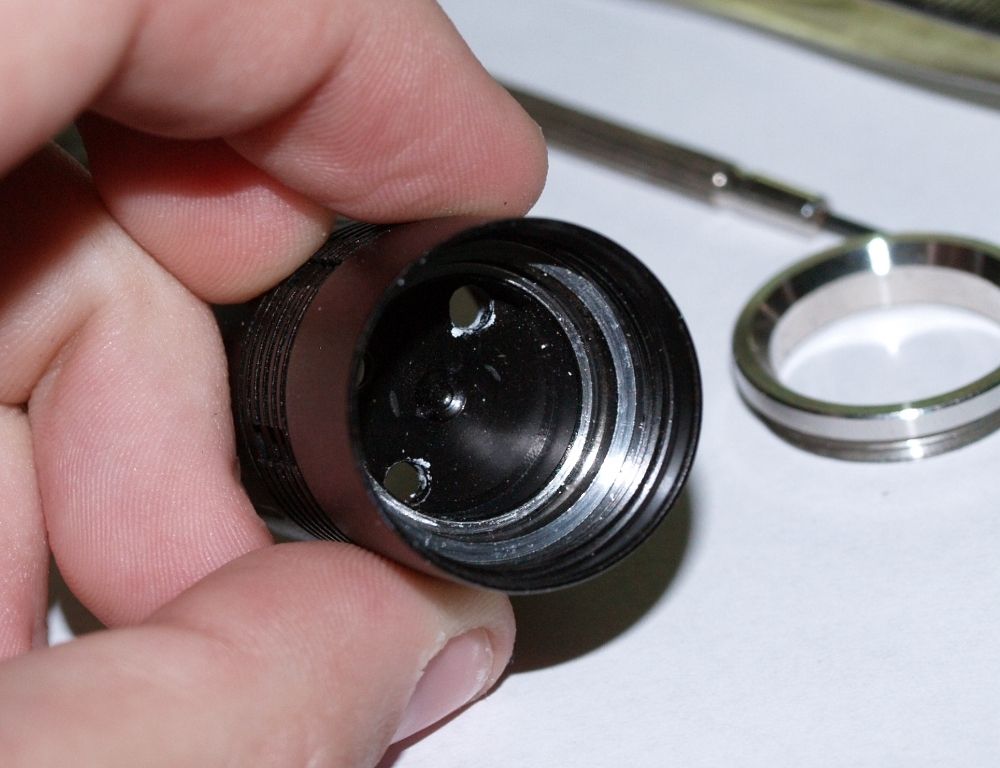
This requires additional modification of the host if you want to fit all your stuff in there! For starters, try to avoid hosts like these. You will usually find information what hosts require modifications in the reviews of the hosts in this section.
Wiring from the board goes into the laser module, either to an actual driver, or directly to the diode (depending on your driver choice).
Reflector Area / Head
This part of the host is usually meant to hold a reflector of the LED assembly. Since this is the space where we have out laser module assembly, we need to get rid of the reflect.
But what then? How do we suspend the laser module within all that empty space?
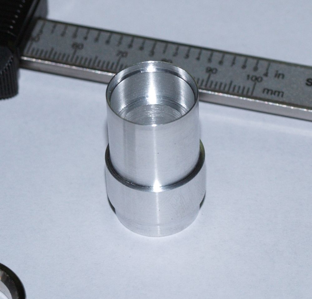
By using a heatsink.
The name can be a little misleading in the start. It's called a heatsink because one of it's roles it to provide cooling for the diode, by acting as a "heat buffer" between the diode, and the environment into which the heat will be dissipated.
Another, more important role of the heatsink is mechanical support of all your components inside.
Some heatsinks have a pill integrated into them:
Heatsink is upside down, showing a spot for 17mm boards.
Such a setup makes entire setup of your laser completely modular. Since you have all your electronics AND laser module in one heatsink, you can swap out entire laser assemblies simply by changing the heatsink with another one!
In practise, people usually have each laser in it's own host, but modular assembly is still very important in troubleshooting, repairs, or upgrades to the laser setup.
Finally, one of the questions that pop up suprisingly often is, "How is the heatsink suspended inside the host, then?"
It's suspended the same way the reflect was supposed to be - it's usually pinched between two parts of the head (or host) that are threaded together.
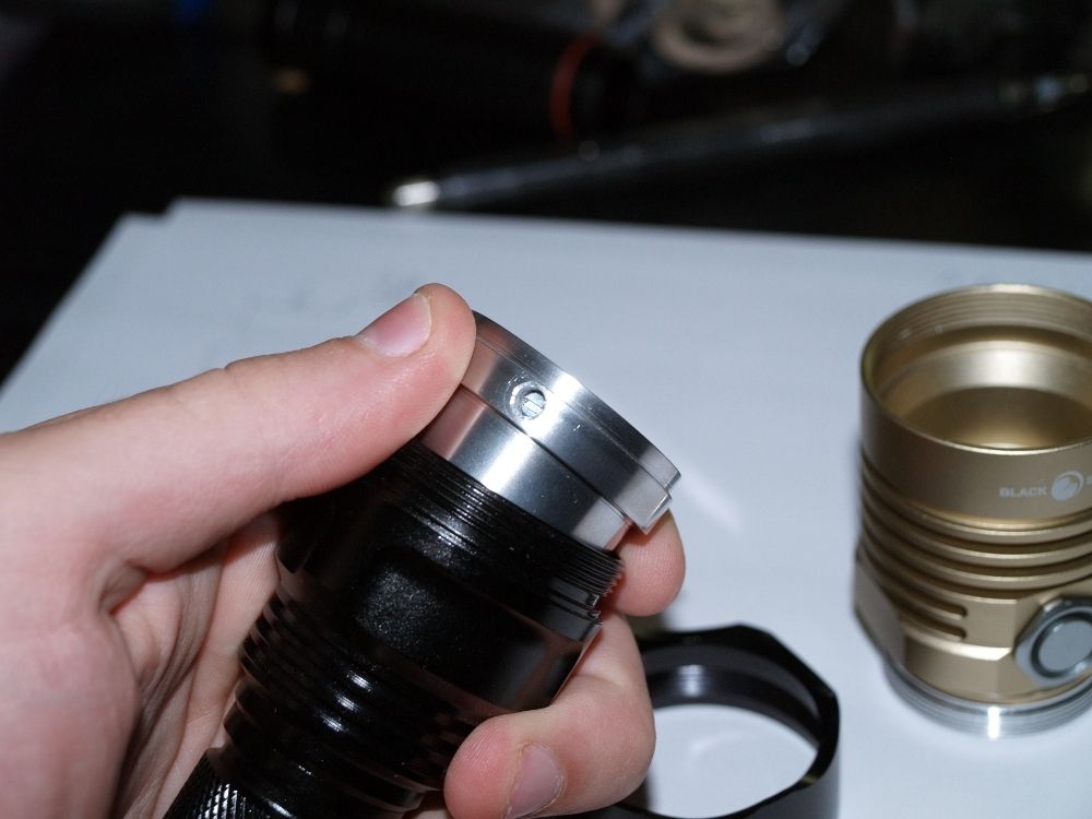
Here, a heatsink is held in-place with a shiny retaining ring:
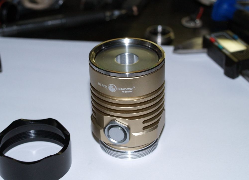
You can even see a retaining ring (or crown) of another host in the lower left corner.
In the case of hosts such as C3 and Q5, which has a head made in such a way that it does not come apart into two, the heatsink is held betweed the head, and the battery barrel.
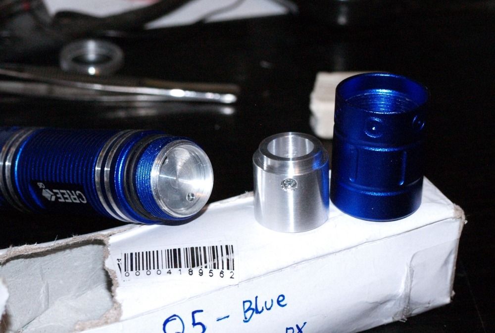
:: How to get the connection to the other end of the battery ::
Yet another common question.
You have your battery touching the contact board or driver in the pill, but what about it's other side?
Here is where the third role of the heatsink comes into play.
A heatsink must provide an electrical connection between the laser module, and the host itself. You'll notice that the hosts are always made of electrically-conductive materials, most commonly aluminium.
That's because the other side of the battery is supported by the tailcap, which connects that side of the battery with entire host.
You need to have the means of obtaining that connection and routing it into the driver. Most common ground connection is made through the diode's "Case" pin, in case-neutral diode builds.
This can get a little confusing so let's break it down.
The operating part of the diode (small, microscopic crystal) has two pins to connect it to the power source. But the operating part is not connected to the metal case on which it is mounted.
When you press the diode into the metal casing, like an Aixiz module, it's case it connected to the module. When you fit that module into the heatsink, another connection is made. When you fit that heatsink into the host, you have a chain connection :
Diode's case <> Casing <> Heatsink <> Host
So entire case of the diode is basically, connected to the other end of the battery in your laser.
And as we previously mentioned, the case of the diode isn't actually connected to the operating part itself. In other words, the "case" pin of the diode has absolutely nothing to do with Positive (+) and Negative (-) pins of the diode.
So to completely boil it down to the simplest point:
Case pin of the diode = the other end of the battery.
Here is a diagram to explain it better. Exeptional thanks to Le Quack!

Exeption:
Ofcourse, this does NOT work with 650nm red diodes extraced from DVD burners, and 808nm IR diodes used in green laser modules.
650nm red diodes are Case negative, which means the Negative(-) input and Case pin of the diode are already connected.
808nm is the opposite, Positive input and Case are connected.
For more diode wiring information, refer to this thread:
http://laserpointerforums.com/f42/meta-topic-pinout-performance-actual-ld-26417.html
This concludes the host intro tutorial.
This thread will be updated with more information as required.
This tutorial will deal with the aspect of housing your laser setup into a portable handheld device. If you require help with the laser setup itself, please view all the sticky threads, tutorials and guides, and if all else fails, send me a Personal Message with your questions and I’ll do my best to get back to you.
Housing a laser into handheld flashlight-alike shell, commonly referred to as “host”, is a lot different than housing it into a project box.
Due to the way flashlight shells are constructed, a lot of work needs to be done, and because of small and usually limited space, you need to be able to solder small parts and work in cramped spaces, have a good spatial awareness regarding the inner workings of the flashlight, and of course, knowledge how to put it all together without breaking anything.
Most commonly, empty shells usually meant for flashlights are used. Some of most common examples include Aurora C6, Ultrafire 501/502b, Guidesman and a lot more others. You’ll notice that these flashlights are made to accept standardized “drop in” modules, like P60. This means that the host allows for modular installation and modification of it’s internal components. Which in turn, means easier job for you.
However, you can't pick up a flashlight simply throw all the components right into it.
Let’s go over few crucial components that make up a flashlight shell and play an integral role in laser assembly.
The Driver Pill

What we refer to as “the driver pill”, is actually a part of the flashlight originally meant to hold the LED emitter and it’s regulation electronics. In most cases it is modular, however if a host already has a pill in it, it means it does not accept standard drop in LED emitter modules. The pill is fitted into the battery barrel, or the head of the host itelf.
We usually use the pill to mount 17mm circuit boards in it. 17mm board can be an entire driver:
http://www.dx.com/p/18v-5w-cree-circuit-board-for-flashlights-16-8mm-5-5mm-26110#.U_JmcqPVBdg
One of my favorites, 1.2 Amps out of the box, great for conservative 445nm builds!
Or just an empty, blank board serving as a contact point for the battery.
Note that wider boards are also posible, like in the picture above, 17mm board is the driver, and 20mm board is the contact PCB (a combination of two options!)
Sometimes, flashlight can have a pill integrated into it's head:

This requires additional modification of the host if you want to fit all your stuff in there! For starters, try to avoid hosts like these. You will usually find information what hosts require modifications in the reviews of the hosts in this section.
Wiring from the board goes into the laser module, either to an actual driver, or directly to the diode (depending on your driver choice).
Reflector Area / Head
This part of the host is usually meant to hold a reflector of the LED assembly. Since this is the space where we have out laser module assembly, we need to get rid of the reflect.
But what then? How do we suspend the laser module within all that empty space?

By using a heatsink.
The name can be a little misleading in the start. It's called a heatsink because one of it's roles it to provide cooling for the diode, by acting as a "heat buffer" between the diode, and the environment into which the heat will be dissipated.
Another, more important role of the heatsink is mechanical support of all your components inside.
Some heatsinks have a pill integrated into them:

Heatsink is upside down, showing a spot for 17mm boards.
Such a setup makes entire setup of your laser completely modular. Since you have all your electronics AND laser module in one heatsink, you can swap out entire laser assemblies simply by changing the heatsink with another one!
In practise, people usually have each laser in it's own host, but modular assembly is still very important in troubleshooting, repairs, or upgrades to the laser setup.
Finally, one of the questions that pop up suprisingly often is, "How is the heatsink suspended inside the host, then?"
It's suspended the same way the reflect was supposed to be - it's usually pinched between two parts of the head (or host) that are threaded together.
Here, a heatsink is held in-place with a shiny retaining ring:

You can even see a retaining ring (or crown) of another host in the lower left corner.
In the case of hosts such as C3 and Q5, which has a head made in such a way that it does not come apart into two, the heatsink is held betweed the head, and the battery barrel.

:: How to get the connection to the other end of the battery ::
Yet another common question.
You have your battery touching the contact board or driver in the pill, but what about it's other side?
Here is where the third role of the heatsink comes into play.
A heatsink must provide an electrical connection between the laser module, and the host itself. You'll notice that the hosts are always made of electrically-conductive materials, most commonly aluminium.
That's because the other side of the battery is supported by the tailcap, which connects that side of the battery with entire host.
You need to have the means of obtaining that connection and routing it into the driver. Most common ground connection is made through the diode's "Case" pin, in case-neutral diode builds.
This can get a little confusing so let's break it down.
The operating part of the diode (small, microscopic crystal) has two pins to connect it to the power source. But the operating part is not connected to the metal case on which it is mounted.
When you press the diode into the metal casing, like an Aixiz module, it's case it connected to the module. When you fit that module into the heatsink, another connection is made. When you fit that heatsink into the host, you have a chain connection :
Diode's case <> Casing <> Heatsink <> Host
So entire case of the diode is basically, connected to the other end of the battery in your laser.
And as we previously mentioned, the case of the diode isn't actually connected to the operating part itself. In other words, the "case" pin of the diode has absolutely nothing to do with Positive (+) and Negative (-) pins of the diode.
So to completely boil it down to the simplest point:
Case pin of the diode = the other end of the battery.
Here is a diagram to explain it better. Exeptional thanks to Le Quack!

Exeption:
Ofcourse, this does NOT work with 650nm red diodes extraced from DVD burners, and 808nm IR diodes used in green laser modules.
650nm red diodes are Case negative, which means the Negative(-) input and Case pin of the diode are already connected.
808nm is the opposite, Positive input and Case are connected.
For more diode wiring information, refer to this thread:
http://laserpointerforums.com/f42/meta-topic-pinout-performance-actual-ld-26417.html
This concludes the host intro tutorial.
This thread will be updated with more information as required.
Last edited:


