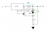
Since I have a few of these, but the potentiometer is rather crap, I'm trying to understand how this circuit works. Specifically how the resistors effect the ma.
I understand how the DDL circuit works where you have just an LM317 voltage regulator, the regulator tries to keep a 1.25 VD between adj and out, so to get the I of the V= IR, you substitute I = V/R, so a 4 ohm resistor = 1.25/4 = 0.3125 amps.
But the Fusion driver seems to be doing something more complicated than that. It has a voltage regulator like DDL's driver (except it uses a TLV1117 instead of a LM317, but I think that's just for efficiency), but it also has something called an Adjustable Micropower Voltage Reference (LM385).
From what I can tell a voltage reference is something like a voltage source, always outputting 1.25v, so assuming that the LM385 is always outputting 1.25v. The thing I'm not quite understanding is how the blu (100k) or red (2.4k) resistors are effecting things.
It appears that the only things in the path of the adj pin on the TLV1117 are the LM385 and the 1k potentiometer (which seems like a rather large value for the max of the potentiometer, 100 (min 12.5 ma) ohm or even 50 (min 25 ma) ohm seems like a good max)
I'm hoping maybe someone can explain what's going on with the 100k/2.4k resistors?


