Welcome to Laser Pointer Forums - discuss green laser pointers, blue laser pointers, and all types of lasers
How to Register on LPF | LPF Donations
Navigation
Install the app
How to install the app on iOS
Follow along with the video below to see how to install our site as a web app on your home screen.
Note: This feature may not be available in some browsers.
More options

You are using an out of date browser. It may not display this or other websites correctly.
You should upgrade or use an alternative browser.
You should upgrade or use an alternative browser.
Trying to build an insane 532 nm laser
- Thread starter Laserbuilder
- Start date


- Joined
- Dec 4, 2016
- Messages
- 197
- Points
- 43
It depends on pulse repetiotion rate. It drops quite quickly after 7-8 kHz, maximum value I'd estimate around 10 kW or less in a single pulse. Average beam power is about 500-1000 mW multimode at the moment. Singlemode will be not more than 500 mW.
- Joined
- Dec 4, 2016
- Messages
- 197
- Points
- 43
At my first experiments I thought that it is enoough to throw a doubling crystal inside the YAG laser and it will be OK and nothing else matters. Unfortunately, no. In the case of a CW or even a QCW laser matters literary everything. To start with, the lamp power supply must give very smooth DC current with minimal ripple factor, otherwise the lamp in the pumping chamber flickers and the laser beam flickers even worse. This leads to poor light stability and great shortage of lamp's life. So I decided to completely rebuild the lamp power supply. I threw away the main power transformer that had aluminium winding and made a new one with copper winding of appropriate thickness, so it doesn't overheat now. I've added a massive filtering capacitor bank with total ~30000 uF capacitance and two massive chokes that form an LCLC filter. I've rebuilt also arc starting circuits and packed everything in a standard rack case. After the rebuild the power unit can give 35A current for more or less long time without overheating with the ripple factor less than 2%, that allowed me to get a smooth and stable laser beam to work with. At the photos you can see both old and new power units.
Old one:
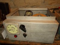
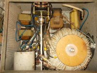
New one:
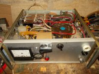
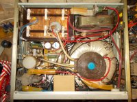
Old one:


New one:


- Joined
- Dec 4, 2016
- Messages
- 197
- Points
- 43
In this post I'll tell about my DIY AO Q-switch controller. The best result of frequency doubled CW laser is got, when the laser is q-switched, to get high peak power of the beam inside the laser resonator. Frequency doubling efficiency is proportional to the square of the beam power, so increasing the peak power by 10 times leads to 100 times better efficiency of SHG. The best method of q-switching in a CW laser is the use of an acousto-optic q-switch, that rapidly deflects the beam from its straight way to the OC or HR mirror, depending on the Q-switch placement, so ot creates high loss factor in the resonator for a brief interval, so the YAG laser rod can store some excess population inversion and burst it out, when the Q-switch is deactivated. I've chosen an MZ-305 AO Q-switch which has 50 MHz operating frewuency. When the HF signal is applied to the Q-switch it is activated and it deflects the laser beam, when the signal is removed -- it doesn't affect the beam.
I didn't have a possibility to get the controller for this q-switch, but had the schemes for one of its modifications, so I've decided to make my own controller based on these. The Q-switch requires up to 30W of 50MHz signal to work properly. For effective work in the laser this signal needs to be modulated by pulses 5 to 10 us in width with adjustable repetition frequency from 2 to 15 kHz, which determins the PRR of the laser. I've developed this controller with the use of very straight and simple vacuum tube circuitry, without a single transistor or microchip. Really, I don't understand why laser manufacturers use now computerized controllers with encrypted communications, when everything can be achieved with a handful of vacuum tubes and resistors.
Developing this controller was quite a mess, until I've packed it in a rack case.
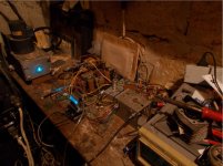
I used my ALC60X laser for testing. Here you can see the beam passing through the q-switch.
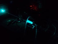
The q-switch splits the beam in multiple fractions when the HF signal is applied.
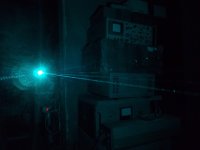
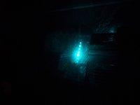
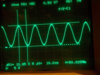
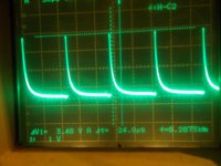
To get proper light pulses, the HF generator must be modulated. The a brief deactivation of the AO q-switch leads to high power light pulse generation. With applied modulation the signal on the q-switch looks like this.
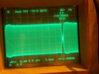
Detailed HF waveform
The modulating pulse
This AO Q-switch controller passed through a couple of stages of modification when tested, and the final one I'll show in the next post.
I didn't have a possibility to get the controller for this q-switch, but had the schemes for one of its modifications, so I've decided to make my own controller based on these. The Q-switch requires up to 30W of 50MHz signal to work properly. For effective work in the laser this signal needs to be modulated by pulses 5 to 10 us in width with adjustable repetition frequency from 2 to 15 kHz, which determins the PRR of the laser. I've developed this controller with the use of very straight and simple vacuum tube circuitry, without a single transistor or microchip. Really, I don't understand why laser manufacturers use now computerized controllers with encrypted communications, when everything can be achieved with a handful of vacuum tubes and resistors.
Developing this controller was quite a mess, until I've packed it in a rack case.

I used my ALC60X laser for testing. Here you can see the beam passing through the q-switch.

The q-switch splits the beam in multiple fractions when the HF signal is applied.


To get proper light pulses, the HF generator must be modulated. The a brief deactivation of the AO q-switch leads to high power light pulse generation. With applied modulation the signal on the q-switch looks like this.

Detailed HF waveform

The modulating pulse

This AO Q-switch controller passed through a couple of stages of modification when tested, and the final one I'll show in the next post.
- Joined
- Dec 4, 2016
- Messages
- 197
- Points
- 43
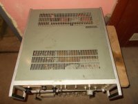
So, in the final version this controller is assembled in a rack case from an old spectrum analyser. It consists of the following blocks: the master quartz oscillator, two-stage pre-amplifier, final power amplifier, pulse modulator and power supply, that gives all neccesary voltages for filament, grids and plates of the vacuum tubes.
The exterior of the AO Q-switch controller:
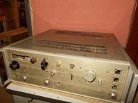
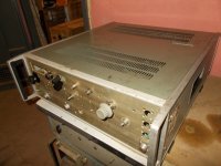
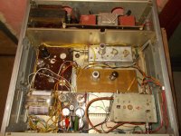
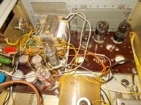
The upper section contains the power supply for the master oscillator, pre-amplifier and modulator. The modulater is mounted on the dark brown circuit board on the left, the master oscillator is inside the aluminium shield box on the right, the pre-amplifier is on the yellow circuit board beneath the master oscillator and the main HF power amplifier is in the bottom right corner. The "plate"power supply for the power amplifier is at left bottom corner, that uses a voltage doubling rectifier, that can supply up to 800 V.
As the controller had undergone through different modofications, some vacuum ubes were added and some of them were removed, so some empty sockets had left on the curcuit boards. The power amplifier plate voltage, PA second grid voltage can be adjusted from the front panel, PRR of the modulator and pulsewidth can be adjusted as well.
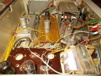
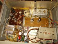
Some detailed views.
The resulting shape of the light pulse from the laser.
The exterior of the AO Q-switch controller:


The upper section contains the power supply for the master oscillator, pre-amplifier and modulator. The modulater is mounted on the dark brown circuit board on the left, the master oscillator is inside the aluminium shield box on the right, the pre-amplifier is on the yellow circuit board beneath the master oscillator and the main HF power amplifier is in the bottom right corner. The "plate"power supply for the power amplifier is at left bottom corner, that uses a voltage doubling rectifier, that can supply up to 800 V.
As the controller had undergone through different modofications, some vacuum ubes were added and some of them were removed, so some empty sockets had left on the curcuit boards. The power amplifier plate voltage, PA second grid voltage can be adjusted from the front panel, PRR of the modulator and pulsewidth can be adjusted as well.

Some detailed views.


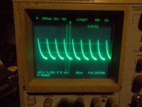
The resulting shape of the light pulse from the laser.

- Joined
- Sep 20, 2013
- Messages
- 20,284
- Points
- 113
At my first experiments I thought that it is enoough to throw a doubling crystal inside the YAG laser and it will be OK and nothing else matters. Unfortunately, no. In the case of a CW or even a QCW laser matters literary everything. To start with, the lamp power supply must give very smooth DC current with minimal ripple factor, otherwise the lamp in the pumping chamber flickers and the laser beam flickers even worse. This leads to poor light stability and great shortage of lamp's life. So I decided to completely rebuild the lamp power supply. I threw away the main power transformer that had aluminium winding and made a new one with copper winding of appropriate thickness, so it doesn't overheat now. I've added a massive filtering capacitor bank with total ~30000 uF capacitance and two massive chokes that form an LCLC filter. I've rebuilt also arc starting circuits and packed everything in a standard rack case. After the rebuild the power unit can give 35A current for more or less long time without overheating with the ripple factor less than 2%, that allowed me to get a smooth and stable laser beam to work with. At the photos you can see both old and new power units.
Old one:
View attachment 73336
View attachment 73337
New one:
View attachment 73334
View attachment 73335
So this went into the case of a spectrum analyzer? Hope it was damaged beyond repair. I remember these from the 1970s and they were expensive back then. Cheap ones sold for $50,000.
- Joined
- Dec 4, 2016
- Messages
- 197
- Points
- 43
So this went into the case of a spectrum analyzer? Hope it was damaged beyond repair. I remember these from the 1970s and they were expensive back then. Cheap ones sold for $50,000.
The AO Q-switch controller went into spectrum analyser case, the lamp power supply went into a NOS rack case of the same width, so I can stack the units one onto another.
- Joined
- Dec 4, 2016
- Messages
- 197
- Points
- 43
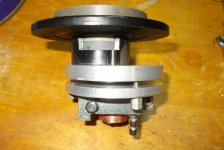
Now its time to tell about the choice of the frequency doubling crystal. After several experiments, that included attempts to use lithium niobate, lithium iodate, barium-sodium niobate, I came to the final option of a doubling crystal. A 532nm converter for a chinese YAG tattoo remover proved to be the best. It contains a large aperture (6*6 mm) crystal plate that is 3 mm thick. I don't know its type, but I think that it is KTP. It is AR coated, so it greatly affects doubling efficiency. It doesn't need thermal stabilisation and it tolerates beam divergence and moderate misalignment very well. And it is very cheap, compared to "real" crystals for scientific use. I costs from 15 to 30$ depending on the seller.
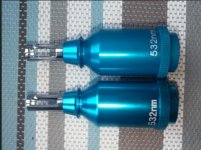
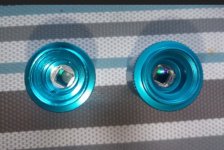
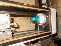
This converter also includes a focusing lens, also AR coated, and it must be removed if you want it for intracavity SHG. In order to place it in my laser head, I had to machine an adapting mount for it, which allows to fix the converter on the OC mirror mount rigidly and align it. The blue tube saves the crystal from dust.
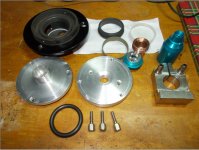
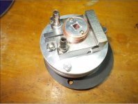
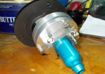
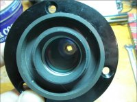

Here the SHG converter with the OC laser mirror are placed in the laser head.
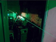
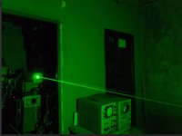
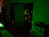
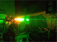
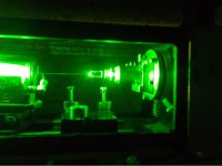
And here it is in action. I estimate the output power of 1.5W peak value at the maximum 40A pumping current and about 1W at 30-32A, that can be maintained more or less stable for some time. I think that this is a good result for my setup at the moment, that uses such a simple and straight-forward engineering approach. The narrow place is the laser pumping chamber itself that can't use the electric power effectively. I hope that I can modify it by installing a bigger YAG rod and getting additional power in 1064nm, that will help me increase the power of SHG.


This converter also includes a focusing lens, also AR coated, and it must be removed if you want it for intracavity SHG. In order to place it in my laser head, I had to machine an adapting mount for it, which allows to fix the converter on the OC mirror mount rigidly and align it. The blue tube saves the crystal from dust.


Here the SHG converter with the OC laser mirror are placed in the laser head.

And here it is in action. I estimate the output power of 1.5W peak value at the maximum 40A pumping current and about 1W at 30-32A, that can be maintained more or less stable for some time. I think that this is a good result for my setup at the moment, that uses such a simple and straight-forward engineering approach. The narrow place is the laser pumping chamber itself that can't use the electric power effectively. I hope that I can modify it by installing a bigger YAG rod and getting additional power in 1064nm, that will help me increase the power of SHG.


- Joined
- Dec 4, 2016
- Messages
- 197
- Points
- 43


