Welcome to Laser Pointer Forums - discuss green laser pointers, blue laser pointers, and all types of lasers

LPF Donation via Stripe | LPF Donation - Other Methods

Links below open in new window

ArcticMyst Security by Avery

The "Clean Edge" Driver - 2.85A driver for pushing 462s (478nm hit so far)

rhd

0
Joined
Dec 7, 2010
Messages
8,475
Points
0
I have successfully removed potting epoxy (the hard black stuff) on driver boards with a hot air tool without having the ICs desolder. I'm still using those drivers until now :) I can give it a try but would stop if there is no sign of the heatsink coming off.

Either way, the priority is scoping it for the switching performance. I'll post updates as I progress on the testing.

Ya, there's no reason to remove the heatsink. It requires the heatsink to run properly. That's part of the driver design.


djQUAN

0
Joined
May 27, 2013
Messages
1,154
Points
63
Re: The "Clean Edge" Driver - 2.85A driver for pushing 462s (478nm hit so far)

Part one: Efficiency testing.

In the pics, the various meters measure the following points:
Yellow DMM = driver input voltage
Red DMM = driver input current
Red digit meter = driver output voltage
Blue digit meter = driver output current

With an 8.40V input voltage (fully charged pair of Li-ION cells) Efficiency is about 92.5% (The low values I got from the previous post was that my powersupply current meter was reading high so I opted to use different meters right at the driver. The meters used here are verified against each other and are well within tolerance.)
attachment.php


With a 7.2V input (Half charged Li-ION pair) Efficiency is at 93.3%
attachment.php


With a 6.0V input (Nearly dead Li-ION pair) Efficiency is at 93.7%
attachment.php


The trend of increasing efficiency at lower battery voltage is explained by the fact that there is less voltage difference between input and output. The smaller voltage difference means less peak currents in the switching devices so we get a tiny bit more efficiency.

Here are some FLIR captures in two input voltages. The driver is run for several minutes to thermally stabilize before the shots were taken.

At 8.4V heatsink side:
attachment.php


8.4V input, looking at the side of the driver. The rectangular part on the upper left of the driver is the main inductor. The hot part is the PCB.
attachment.php


At 6.0V heatsink side:
attachment.php


6.0V looking at the side of the driver.
attachment.php


Oscilloscope testing will follow on next post...
 

Attachments

  • IMG_5927.jpg
    IMG_5927.jpg
    262.7 KB · Views: 258
  • IMG_5928.jpg
    IMG_5928.jpg
    264.6 KB · Views: 263
  • IMG_5929.jpg
    IMG_5929.jpg
    253.7 KB · Views: 253
  • FLIR0234.jpg
    FLIR0234.jpg
    39 KB · Views: 208
  • FLIR0236.jpg
    FLIR0236.jpg
    36.4 KB · Views: 172
  • FLIR0237.jpg
    FLIR0237.jpg
    36.4 KB · Views: 248
  • FLIR0238.jpg
    FLIR0238.jpg
    36.1 KB · Views: 256

djQUAN

0
Joined
May 27, 2013
Messages
1,154
Points
63
Re: The "Clean Edge" Driver - 2.85A driver for pushing 462s (478nm hit so far)

Part two: Startup and ripple measurements

The dummy load is a series string of 4 1N5401 diodes and a 0.5 Ohm 4 terminal precision resistor (where I tapped off the signal for the oscilloscope)

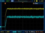
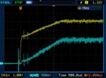
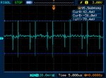
Yellow trace is driver output voltage,
Blue trace is driver output current 0.5V = 1A of current.
Oscilloscope is set to long memory to more easily capture very fast spikes which also results to the trace looking noisier than it really is.

Startup is pretty clean with no unwanted current spikes.
attachment.php


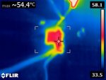
At 8.4V input, the driver voltage rises abruptly since at this moment, the diodes are not yet conducting. Once the diodes conduct, The voltage then slows down to maintain output current. There is about 2.5ms of soft start before the current stabilizes to the set value. (The small spikes at the very beginning are not from the driver. They are caused by contact bounce of the relay in my bench supply when the output is turned on.)
attachment.php


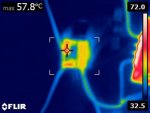
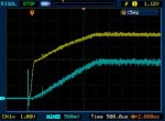
At 7.2V input, the results are similar as above. The trace is a little less fuzzy as the smaller voltage difference results to lower peak currents in the power devices.
attachment.php


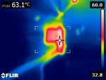
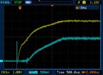
At 6.0V input, the output voltage rise when the diodes aren't conducting slows down. Soft start is delayed by about 250us or so but still good. There is even less noise in the traces.
attachment.php


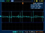
Now we look at output ripple.

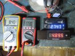
At 8.4V the current spikes show up. The converter is running at about 110kHz. There is about 202mA peak to peak of output ripple current.
attachment.php


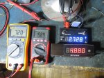
At 7.2V, the switching frequency drops to about 95kHz. Output ripple current lowers to about 156mA peak to peak.
attachment.php


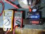
At 6.0V, the switching frequency drops further to about 64kHz. Output ripple current lowers to about 124.8mA peak to peak.
attachment.php


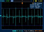
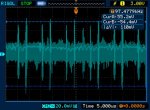
With infinite trace persistence, we can see that, besides the current spikes due to the switching devices, there is also some random ripple noise of a much lower frequency that modulates the current up and down.
This measurement was taken at 7.2V input but it appears to be the same at different input voltages. This low frequency modulation (the thick fuzzy part of the trace) is about 64mA peak to peak.
attachment.php


I think the driver startup is pretty clean with a very short startup which means instant brightness at turn on. The output is a little noisy ripple wise but still a small percentage of the total output current. Do keep this in mind though when driving the diode near its limits as the ripple current at high battery voltages might be enough to take it "over the edge" :)
 

Attachments

  • NewFile0.jpg
    NewFile0.jpg
    39.7 KB · Views: 210
  • NewFile1.jpg
    NewFile1.jpg
    38.8 KB · Views: 264
  • NewFile2.jpg
    NewFile2.jpg
    37.5 KB · Views: 253
  • NewFile3.jpg
    NewFile3.jpg
    37.5 KB · Views: 243
  • NewFile6.jpg
    NewFile6.jpg
    49.6 KB · Views: 261
  • NewFile7.jpg
    NewFile7.jpg
    47 KB · Views: 252
  • NewFile8.jpg
    NewFile8.jpg
    46.8 KB · Views: 256
  • NewFile9.jpg
    NewFile9.jpg
    47.7 KB · Views: 253
Last edited:

rhd

0
Joined
Dec 7, 2010
Messages
8,475
Points
0
Re: The "Clean Edge" Driver - 2.85A driver for pushing 462s (478nm hit so far)

Wow! First and foremost, thank you for such thorough testing. You really put a lot of work into that torture test. I'm really grateful. It's neat to see something you've designed "on paper" / "in your head" (ie, without a scope, FLIR, other tools etc) put to the test, and seeing FLIR images is just awesome. Thanks!

I'm thrilled by that efficiency, and by the clean startup. Operating ripple is fine, but just par for the course. Although we haven't seen independent scoping of other laser bucks, I suspect that this isn't that much better. It's not the sub-50mA I as hoping for.
 

djQUAN

0
Joined
May 27, 2013
Messages
1,154
Points
63
Re: The "Clean Edge" Driver - 2.85A driver for pushing 462s (478nm hit so far)

You're welcome. The bench setup is still there so if you want me to test something specifically. I may also be able to test repeated on-off-on cycling without contact bounce at different rates but that would take a while as I need to build a switching interface that will connect to my signal generator.

I think I need a proper test load if I'll be doing more driver tests in the future. My rigged test load is toasty during the test but luckily survived. :)
attachment.php
 

Attachments

  • FLIR0235.jpg
    FLIR0235.jpg
    32.4 KB · Views: 247


Top