

I am still somewhat of a newbie here. Here are a couple of projects that I made. I call them my “red neck” phasers because my machine shop consists of a 1/2” VSR hand drill; a 12mm hand reamer; a homemade alignment jig made for “aiming” the module as the epoxy holding the module sink cures; and various files for shaping the heat sinks for fit. I'm sure there are more refined ways to accomplish this, but simple functionality was my primary concern. I'll add photos and a description of each unit.
Type I Phaser from Star Trek – The Next Generation:
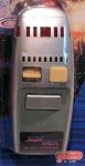
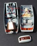
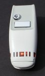
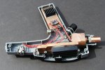
I started with a Galoob toy phaser purchased from E-Bay and modified the body considerably (check photos). I made a hole in the “emitter” large enough for the beam.
The system uses a Mitsubishi 660nm diode and adjustable driver purchased from AixiZ as a kit. Part number: AIX-445-KND (the page states 650nm, but the spec sheet delivered with the diode states 660)
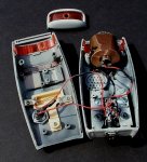
I set the driver at 300mW and attached it to a piece of copper strap that is attached to the body of the phaser. On the back side of that strap, I attached a couple of RAM heat sinks, using Arctic Silver adhesive. The RAM sinks actually reside in the battery compartment.
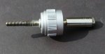
The diode was set into a 12mm AixiZ copper module and pressed into a sink made from 1-1/8” copper bar that I modified to fit within the limited space of the body. The heat sink was then attached to the body with an epoxy (J.B. Weld). I made an alignment jig from an AixiZ module that I bored out enough to install a long bolt into. With that jig, I was able to align the beam path fairly accurately by aligning the bolt and keeping it in position until the epoxy hardened.
I installed a keyed lockout at the rear of the unit and made use of the existing “fire” button. I considered it more than adequate for the low current draw of the laser.
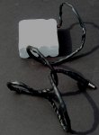
As with other phasers I am building, the power is from an external Li-ion 8800mAh battery pack and is supplied by means of a plug / receptacle setup. The receptacle is at the rear of the battery compartment.
The unit works well and fires the beam through the center hole in the emitter, so removal of the emitter is only necessary when a change of focus is required. An added benefit is that reflected light from the module tends to cause the emitter to glow as a beam is firing.
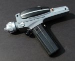
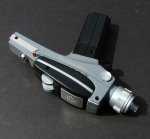
Star Trek – The Original Series Type I / II phaser:
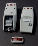
This is a variation of a Bluray phaser that I saw on Kipkay.com.
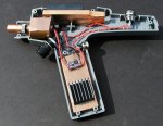
I started with the exact toy phaser used in the Kip Kay project, but used and M-140 diode purchased from DTR and aimed for a much longer duty cycle than the Kip Kay phaser. I ended up pretty much gutting everything inside the body, plus cutting out of filing off many of the molded internal “holders” inside the body.
All components were attached to the plastic body with J. B. Weld and all cooling components were attached to each other with Arctic Silver adhesive.
The copper 12mm AixiZ module is installed into a piece of 1-1/8” copper rod that was modified to fit within the confines of the body. I used a 12mm hand reamer to finish the hole for the module and the fit is very tight, so I used no adhesive or set screw to hold the module. It is press fit. I attached a piece of 1/4” copper tubing to the end of the focus knob in order to extend it outside of the closed body of the phaser, so that it can be turned. During the curing of the epoxy, I used an alignment jig (see photo) that I had made for proper beam alignment so that removal of the “emitter” is only necessary when a change of focus is required. The emitter simply screws off.
Above the copper rod that holds the module, I attached a piece of copper strap, again modified to fit. Attached to the top of the strap are two aluminum RAM sinks to provide a little air cooling.
I chose the new X-Drive V6 1.8 amp Buck driver (by Lazeerer) and purchased from Cajun Lasers. I attached it to another piece of the copper strap, which I placed in the battery compartment. Attached to the copper strap is another RAM sink.
As with my other phaser, I added a keyed lockout and placed it where one of the toy's control knobs had been. Near the top of the hand grip, I installed a power receptacle to accept the plug from my Li-ion battery pack.
I was pleasantly surprised by this setup and especially by the driver. Lazeerer stated the the driver runs cool. That is an understatement. At 1.8 amps, I held the driver between my fingers and fired it for almost 10 seconds before I could even feel which side of the driver needed to be attached to the sink.
After a coupe of minutes of continuous power, the module and driver were not much over the ambient air temp. I think that the amount of copper I used amounted to serious overkill. One benefit of the copper is the weight. This phaser is similar in weight to my Walther PPK. It does not feel like a toy.
The beam fires exactly through the center of the emitter and reflected light from the module causes the clear plastic to glow during firing. Although it's not very pretty inside, it works quite well.
Type I Phaser from Star Trek – The Next Generation:
I started with a Galoob toy phaser purchased from E-Bay and modified the body considerably (check photos). I made a hole in the “emitter” large enough for the beam.
The system uses a Mitsubishi 660nm diode and adjustable driver purchased from AixiZ as a kit. Part number: AIX-445-KND (the page states 650nm, but the spec sheet delivered with the diode states 660)
I set the driver at 300mW and attached it to a piece of copper strap that is attached to the body of the phaser. On the back side of that strap, I attached a couple of RAM heat sinks, using Arctic Silver adhesive. The RAM sinks actually reside in the battery compartment.
The diode was set into a 12mm AixiZ copper module and pressed into a sink made from 1-1/8” copper bar that I modified to fit within the limited space of the body. The heat sink was then attached to the body with an epoxy (J.B. Weld). I made an alignment jig from an AixiZ module that I bored out enough to install a long bolt into. With that jig, I was able to align the beam path fairly accurately by aligning the bolt and keeping it in position until the epoxy hardened.
I installed a keyed lockout at the rear of the unit and made use of the existing “fire” button. I considered it more than adequate for the low current draw of the laser.
As with other phasers I am building, the power is from an external Li-ion 8800mAh battery pack and is supplied by means of a plug / receptacle setup. The receptacle is at the rear of the battery compartment.
The unit works well and fires the beam through the center hole in the emitter, so removal of the emitter is only necessary when a change of focus is required. An added benefit is that reflected light from the module tends to cause the emitter to glow as a beam is firing.
Star Trek – The Original Series Type I / II phaser:
This is a variation of a Bluray phaser that I saw on Kipkay.com.
I started with the exact toy phaser used in the Kip Kay project, but used and M-140 diode purchased from DTR and aimed for a much longer duty cycle than the Kip Kay phaser. I ended up pretty much gutting everything inside the body, plus cutting out of filing off many of the molded internal “holders” inside the body.
All components were attached to the plastic body with J. B. Weld and all cooling components were attached to each other with Arctic Silver adhesive.
The copper 12mm AixiZ module is installed into a piece of 1-1/8” copper rod that was modified to fit within the confines of the body. I used a 12mm hand reamer to finish the hole for the module and the fit is very tight, so I used no adhesive or set screw to hold the module. It is press fit. I attached a piece of 1/4” copper tubing to the end of the focus knob in order to extend it outside of the closed body of the phaser, so that it can be turned. During the curing of the epoxy, I used an alignment jig (see photo) that I had made for proper beam alignment so that removal of the “emitter” is only necessary when a change of focus is required. The emitter simply screws off.
Above the copper rod that holds the module, I attached a piece of copper strap, again modified to fit. Attached to the top of the strap are two aluminum RAM sinks to provide a little air cooling.
I chose the new X-Drive V6 1.8 amp Buck driver (by Lazeerer) and purchased from Cajun Lasers. I attached it to another piece of the copper strap, which I placed in the battery compartment. Attached to the copper strap is another RAM sink.
As with my other phaser, I added a keyed lockout and placed it where one of the toy's control knobs had been. Near the top of the hand grip, I installed a power receptacle to accept the plug from my Li-ion battery pack.
I was pleasantly surprised by this setup and especially by the driver. Lazeerer stated the the driver runs cool. That is an understatement. At 1.8 amps, I held the driver between my fingers and fired it for almost 10 seconds before I could even feel which side of the driver needed to be attached to the sink.
After a coupe of minutes of continuous power, the module and driver were not much over the ambient air temp. I think that the amount of copper I used amounted to serious overkill. One benefit of the copper is the weight. This phaser is similar in weight to my Walther PPK. It does not feel like a toy.
The beam fires exactly through the center of the emitter and reflected light from the module causes the clear plastic to glow during firing. Although it's not very pretty inside, it works quite well.
Attachments
-
 Alignment-Jig-s.JPG208.9 KB · Views: 719
 -
 Galoob Phaser-s.jpg54.2 KB · Views: 508
 -
 Battery-Pack-s.JPG178.6 KB · Views: 410
 -
 TNG-Type-01-Internal-01s.JPG261.2 KB · Views: 615
 -
 TNG-Type-01-Internal-02s.JPG244.6 KB · Views: 818
 -
 TNG-Type-01-Internal-back-01s.JPG207.8 KB · Views: 1,520
 -
 TNG-Type-01-Externals.JPG136.7 KB · Views: 388
 -
 TOS-Type-02-Internal-01s.JPG386.3 KB · Views: 6,072
 -
 TOS-Type-02-Internal-02s.JPG357 KB · Views: 2,407
 -
 TOS-Type-02-External-01s.JPG336.6 KB · Views: 832
 -
 TOS-Type-02-External-02s.JPG294.2 KB · Views: 1,503
Last edited by a moderator:


")