Welcome to Laser Pointer Forums - discuss green laser pointers, blue laser pointers, and all types of lasers

LPF Donation via Stripe | LPF Donation - Other Methods

Links below open in new window

ArcticMyst Security by Avery

Shunt to reduce power?

aiello

New member
Joined
Feb 25, 2021
Messages
25
Points
3
I got a cheapish blue module to use as part of an RGB light show. It was advertised as 1W but turned out to be way over-powered (est. 2+W, burns wood and gets hot!)

The driver doesn't have a potentiometer to regulate the current. Can I reduce the power of the diode by simply shunting some of its current (resistors parallel to LD)?

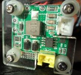
Or does anyone know how to reduce the current on this driver board (see attached photo)?
 

Attachments

  • mod1.jpg
    mod1.jpg
    130.3 KB · Views: 12
Last edited:


farbe2

Well-known member
Joined
Oct 3, 2018
Messages
303
Points
63
You could also measure the voltage across the shunt resistor and determine the current this way.
If you have the current you could calculate a new shunt resistor for less power.

Connecting a resistor in parallel with the LD works too, however the module would use the same power and instead of the module, your parallel resistor would get blisteringly hot. The parallel resistor would use all the power that you dont want inside the LD thus wasting energy.
 

aiello

New member
Joined
Feb 25, 2021
Messages
25
Points
3
Yes, by shunting I meant resistors parallel to the LD. The diode and driver don't mind I hope?

It would waste energy, but I need to reduce the light output to match the red and green lasers, and reduce heat in the diode. It would be much better to modify the driver.
 
Joined
Sep 20, 2013
Messages
17,389
Points
113
These drivers are current regulators, not voltage regulators, so no I wouldn't try it. The laser diode changes its forward voltage as it heats up and a resistor would not make the driver able to regulate properly. Finding the sense resistor on the board and changing it to reduce the current is the best you can do unless you are willing to replace the driver board. In fact, that would be your best bet. Get a buck driver that is adjustable and go from there.
 

aiello

New member
Joined
Feb 25, 2021
Messages
25
Points
3
For simplicity I just tried it... voltage on LD was about 4.64 Volts, four 22 Ohm resistors in parallel (5.5 Ohms) reduced it to 4.33 Volts, where they waste about 3.4 Watts.

Laser output is now roughly equal in brightness to the red laser. Resistors get quite hot though, may have to use eight 11 Ohm ones maybe.
 

Mihut84

New member
Joined
Jan 25, 2022
Messages
2
Points
1
The 4th pin, lower left corner is the feedback pin, which is connected to the negative terminal of the laser diode, and to a resistor that goes to ground, that is the feedback resistor that dictates the current. After you find that, for setting the current you have I = Vfb/Rfb, Vfb=0,2V
 

Giannis_TDM

Well-known member
Joined
Apr 27, 2019
Messages
896
Points
93
For simplicity I just tried it... voltage on LD was about 4.64 Volts, four 22 Ohm resistors in parallel (5.5 Ohms) reduced it to 4.33 Volts, where they waste about 3.4 Watts.

Laser output is now roughly equal in brightness to the red laser. Resistors get quite hot though, may have to use eight 11 Ohm ones maybe.
or you can also remove the 160milliohm shunt from the board and replace it with a 320milliohm shunt, which will halve the current without making excess heat.
1643207717383.png
this is what you need to replace.
https://lcsc.com/product-detail/Cur...s_Ever-Ohms-Tech-CR1812FR330E04R_C175936.html
and this will be the appropriate replacement.


Top