Welcome to Laser Pointer Forums - discuss green laser pointers, blue laser pointers, and all types of lasers

LPF Donation via Stripe | LPF Donation - Other Methods

Links below open in new window

ArcticMyst Security by Avery

Self-mixing laser diode vibrometer.

Joined
Feb 25, 2014
Messages
3
Points
0
Hello everyone!
I'm new to this forum and I'm excited to be here!.

I currently working on to make a self-mixing laser diode vibrometer to measure sound from a loudspeaker.

I've a schematic over a setup but I have some questions about it.

1. Where should I make the output measurements from the schematic? my guess is between photodiode and plus?.

2. Can I just record the output from the setup into an audio interface to record the sounds? or do I need to de-modulate the signal somehow?

Best! :)


Joined
Feb 25, 2014
Messages
3
Points
0
Here is a picture of the schematic.
 

Attachments

  • Skärmavbild 2014-02-26 kl. 01.48.16.png
    Skärmavbild 2014-02-26 kl. 01.48.16.png
    42.2 KB · Views: 727
Joined
Feb 25, 2014
Messages
3
Points
0
I found the schematic from a paper about measurements. The laser diode will send a laser beam against the moving object. When the beam hits the surface the backscattered light will be mixed up in the laser diode cavity and this will make that the signal going from the Photo diode will contain the mixed signal.
 
Joined
Oct 3, 2011
Messages
899
Points
0
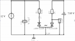
I think the output is the diagram labeled 2 just to the right of the of the photodiode on the right. It's the small rectangle that has a connection above the right diode and ground. Off to the left of it in charachters I cannot recreate here well are o10 with a diagonal line through the larger 0. That would make sense to me as it's the only place in the diagram that is open between a potentially variable voltage/current point and ground. I suspect you will measure output in milivolts. Changing the R2 3k resistor to a 10k pot would give you a degree of "calibration" or gain controll I think too, which may be useful if you were going to use the output for something besides measurement (I.e. The recording device you mentioned)

Disclaimer- my knowledge of schematics is amatuer at best and my previous experience is several years of building DIY audio stuff. I'm not too savvy with electronics but after years of building audio stuff from schematics and trying to learn what's actually going on with them in the process I think I have a pretty decent foundation in understanding simpler stuff like this. It's a very simple and cheap circuit to build and worse case scenario is you try it and waste a couple dollars in the process.

Which photo diode is used to measure the optical reflection? I'm not sure what you are exactly trying to accomplish with this circuit, can you give a more detailed description of your application? Are you trying to measure frequency response? You mentioned "mixed up in the laser diode cavity" which really throws me off. I don't see how that is going to happen. What I envision you doing with something like this is pointing your laser onto the moving object (audio driver) which will cause the reflected light to move around onto the field it is reflected to. I presume you would try to put one (or both) photodiodes onto this reflected field to gather some of the reflected laser light. I can see where that might give some variable output that would be proportional to the movement of the audio driver.

It looks like a novel idea but I cannot see how this would provide any useful information on frequency response of a driver that could be applied to designing a loudspeaker (which would be my interest in something like this) because it would not take into consideration the effects of the baffle, interaction between drivers, and the room. It would only give the response curve of the moving driver surface which does not equate to ultimate audio response of the driver (which is a system that includes baffle, room, etc).

Can you provide a link to the paper where you found this schema?

I will be very interested to see what you do with this and how it works. I can see how it might be used in something like one of those laser listening spy devices. Shooting a laser onto a window and measuring the vibrations and converting them back into sound.

Keep us updated on your progress please.
 
Joined
Oct 3, 2011
Messages
899
Points
0
Edit- looking at the schema again I realize I made a mistake or assumption. I did not pay close attention to the diode on the left. I didn't realize it was a laser diode. I thought it was another photodiode. Now that I see this I understand a little better what you were saying about the light being "mixed up" in the laser diode cavity. Before I saw this I was thinking the laser diode wasn't a part of the circuit and wouldn't have any interaction with it. Now I realize that's not the case and this schematic has become much more interesting and dynamic. I'm really unclear now on what it's used for but it does intrigue me even more. Are you certain the reflected light from the laser is somehow "sensed" or picked back up by the laser diode itself? This is way outside my understanding of laser diodes. I would not think the source diode would act as some sort of sensor itself, just the emitter of light. I could be wrong here. I would think, unless the LD was placed very close to the moving surface and gathered a very significant portion of the back reflected laser light, it would not act as a "receiver". I do know. LD's can be damaged by back reflected light, I've killed a couple by placing them directly against a reflective surface. Maybe someone with a better understanding of the dynamics of a laser diode will chime in here. If it were acting as a receiver of some kind then the laser light going back into the laser diode cavity would have to change the dynamics of the diode (I guess voltage across) in a way that was significant enough to be useful in this cirsuit.

What type of laser diode and power levels were you planning to use here?


Top