Welcome to Laser Pointer Forums - discuss green laser pointers, blue laser pointers, and all types of lasers

Buy Site Supporter Role (remove some ads) | LPF Donations

Links below open in new window

FrozenGate by Avery

Right driver for dvd-burner diode?

bbummi;

You can get it more compact.

Here is one I did on a ~20mm pc board:

317Driv.JPG


Had to insulate & trim the LM317 a little.

LarryDFW

That is the most brilliant mod.. can you explain the resistors and the lm317, schematic if u could ?
Lets say i want to make a 300mA fixed output, what mods do i need to make to the DDL ?


1.25/A = ohms

So if you want a 300 mW fixed output, use a 1.25/0.3 = 4.167 ohms. The "1.25" is a constant derived from the LM317 spec sheet, the "0.3" is 300 mA expressed as a decimal. You'll probably not find a 4.166666 ohm resistor, but a 4 ohm resistor would give you 312 mA. If you used a 4 ohm+5 ohm resistor in parallel, that would give 4.5 ohms and a limit of 277 mA.

Greg


Greg
 
Okay great! now i understand..
heres what i understand.. Firstly as the pic posted by larryFW, i will eliminate the 100Ohm VR.. remaining circuit remains the same ..and the resistor values that i plan to use will be 4Ohms so will that give me just about 300mA ?
Pic attached..
 

Attachments

  • LM317_components01_001.jpg
    LM317_components01_001.jpg
    61.6 KB · Views: 8,033
Yeah, that oughtta do it. 4 ohm resistor would give you 317 mA - about 5% more than the 300 you plan for. Keep in mind some cheap resistors can be +/- 10% or 5% tolerence so that 4 ohm might be as high sa 4.4 or as low as 3.6 ohm. If you have a digital multimeter, be sure to test the resistor first and pick the one closest to the resistance value you want. The ones I use are the retail NTE 2% resistors, so usually not that much variance with mine.
 
Last edited:
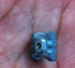
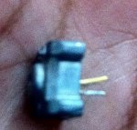
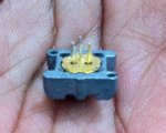
Thanks Hammong, Would very much appreciate if anyone tells me what kind of diode is this that i have in the picture.. and how much current should i set it with while using just the aixiz module heatsinkining, And i want it with no overheating or something like that with duty cycles more than 3~5minutes.. And it wont hurt the diode.. Pic is attached, It is the closest view i can get on a iphone camera..

P.S: It is open can diode, from a DVD-RW 22X
 

Attachments

  • IMG_0013.JPG
    IMG_0013.JPG
    122.8 KB · Views: 330
  • IMG_0016.JPG
    IMG_0016.JPG
    199.8 KB · Views: 424
  • IMG_0018.JPG
    IMG_0018.JPG
    224.1 KB · Views: 643
Last edited:
No idea what diode that is, since it's still inside a piece of the sled heatsink. As for starting current, you should build or buy a variable current driver, and start at 0mA and slowly go up until the diode diode suddenly gets brighter ... That's the threshold current. Report back with what you find - it should be somewhere between 15mA and 60mA. Generally, the higher power the diode is, the higher the Ith.
 
It is an open can, exactly same as this one.. I have quite a guess that its LPC-815 diode, So i would suppose, if you can give me a rough idea about the previously mentioned question, much appreciated!
 
The LPC-815 is an open can, long die diode. If that's indeed what you have there, it's a nice diode and capable of some good output. Here's a summary of what I found on another forum:

* 360mA = 220mW
* 390mA = 235mW
* 420mA = 250mW
* 435mA = 265mW
* 460mA = 275mW- 280mW

I make no warranty or claim for the info. Use values at your own risk. The quoted "long-life" current for that diode was 420 mA.

Greg
 
Last edited:
The LPC-815 is an open can, long die diode. If that's indeed what you have there, it's a nice diode and capable of some good output. Here's a summary of what I found on another forum:

* 360mA = 220mW
* 390mA = 235mW
* 420mA = 250mW
* 435mA = 265mW
* 460mA = 275mW- 280mW

I make no warranty or claim for the info. Use values at your own risk. The quoted "long-life" current for that diode was 420 mA.

Greg

if my calculations are correct you need 7 omh resistance on 3 V battery to get 420 mA
And on 7.2 volts(which is recommended output for daedal circuit based on LM317) you need 17 ohms

Since some daedal circuits have 2 10 ohm resistors you will need 8.4 V on 20 omh resistance
I prefer 9 volts since DC diode can cause in some voltage drop as far as i heard.
So with daedal circuit using 100 omh potenciometer,LM317,2 x 10 omh resistors,47 uf 35 v capacitor and 1N4007/1 you will need 9 volts for optimal 420 mA work.
Now i dont know why you need resistor if you have 100 ohm potenciometer

So if you take out those 2 resistors you will need just 3 volt battery and resistance set on 7 on potenciometer.
 
The two 10 ohm resistors in parallel are to set the maximum output current of the driver. True, you could just use the pot, but if you twitch while setting it, you could easily overshoot the set point and send way too much current through to the diode.

Agree with the 9v drive voltage into the circuit.

Your resistor value of 17 ohms sounds wrong. The LM317 will limit to 420mA with 2.97 ohms between the two set pins. Input voltage is unimportant as long as its high enough to drive the circuit and diode.

Yeah i still have problem understanding the LM317
Still its good driver cause it sets CC(constant current) while batteries have Constant Voltage which is bad.
I guess my formula works that way that every few minutes you have to set the resistance cause i didnt calculate the LM317 in this.

Can you give me the formula to calculate Amps that LM317 gives with specific resistance.?
 
From the National Semiconductor spec sheet, the formula is 1.25/A = ohms. Be sure to specify milliamperes as a decimal, eg 420 mA = 0.42 A
 
From the National Semiconductor spec sheet, the formula is 1.25/A = ohms. Be sure to specify milliamperes as a decimal, eg 420 mA = 0.42 A

Thank you.
BTW i was thinking to make pot lock which will make you unable to set the resistance in pot until you remove the locket.
Still thinking ABOUT the design.
Still those mini pots with screw on top sound easy to lock while massive are hard to.

BTW now if i only need 2.9 omh resistance to get 420 mA How the hell am i going to achieve this with 2 of 10 omh resistors in the circuit?
 
Last edited:
No. Just plain "NO". Do not rely on some mechanical limitation on that pot to set the minimum resistance it will deliver. If the mechanical limit fails, bends, breaks off, etc, your laser diode is going to go POOF. Furthermore, we're talking about the difference of FRACTIONS of 1 ohm being enough to cook your diode. 2.9 ohms might be OK, 2.8 ohms is going to give you 10% more power. That's a really narrow range.

Do the right thing, and figure what the MAXIMUM current you want to deliver is, and put the appropriate resistor in series with the pot to guarantee it won't exceed that value. Then, if you zero the pot, you have nothing to worry about.

Go to Mouser Electronics' web site and look at the available resistor values. There's no such thing as a 5 ohm resistor - which is why the original design used two 10-ohm resistors in parallel, which GIVES you 5 ohms (1 / 2x10 = 5 -- part of Ohm's law).

You can buy a 2.7 ohm resistor or a 3.0 ohm resistor. I'd go for the 3.0 resistor and drive the diode a little UNDER your 420 mA goal.

Greg

Aha so putting 2 resistors in parallel lowers the resistance

Still 5 omhs are too much i loose alot of power.
i think i wanna keep the resistance on 3 omhs cause i only loose little power so its still near 250 mW.
 
Last edited:


Back
Top