just to update, emphasize, and reinforce a few other posts I've made:
With most drivers, 1K or so in parallel will discharge the cap plenty fast but not materially affect the circuit.
You can figure the extra current it will draw: in parallel with a 4V laser diode, 1K ohms would draw 4mA, not that much more load for your driver.
And according to this RC Time Constant Calculator, a 1K resistor will discharge a 10uf cap to only 10% of its charge in 23 milliseconds. (and to 1% in 46 msec)
And here's a very reliable, sturdy way to do it:
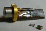
The photo below shows my crude prototype - it's merely a small piece of 2-sided pc board, with 2 holes drilled through it. In one hole I've pressed a size 0603, 1.2K ohm resistor; in the other is a similar-sized 4.7uf capacitor. So the R and the C are each in parallel with the 2 sides of the board. While soldering the parts in, I tinned the whole board so that when connecting the diode it will take minimal heat.
All that needs to be done is to wedge the board between the 2 diode pins, then solder them with a quick touch. The driver circuit can then be soldered to the other end of the protection board.
This board is small enough - and sturdy enough - to be trimmed to your desired length using wire cutters.
Need more capacitance? Drill more little holes and plug 'em up.
Of course if designing your own board, if it's a direct-solder to the LD you can just add the resistor to the design.
[in the photo, the board is in place on the LD but not soldered to it. The parts in the foreground are 1.2K resistor, left; and 4.7uf 6.3V capacitor on the right. My board was roughly cut and poorly soldered but I hope it shows the potential for this approach]
I hope this helps save some laser diodes!
")
DanQ
blown another diode,
even though you're using a protection capacitor?
==> put a resistor in parallel with that cap! <==
you can use a surface-mount, between the diode pins!
even though you're using a protection capacitor?
==> put a resistor in parallel with that cap! <==
you can use a surface-mount, between the diode pins!
With most drivers, 1K or so in parallel will discharge the cap plenty fast but not materially affect the circuit.
You can figure the extra current it will draw: in parallel with a 4V laser diode, 1K ohms would draw 4mA, not that much more load for your driver.
And according to this RC Time Constant Calculator, a 1K resistor will discharge a 10uf cap to only 10% of its charge in 23 milliseconds. (and to 1% in 46 msec)
And here's a very reliable, sturdy way to do it:
The photo below shows my crude prototype - it's merely a small piece of 2-sided pc board, with 2 holes drilled through it. In one hole I've pressed a size 0603, 1.2K ohm resistor; in the other is a similar-sized 4.7uf capacitor. So the R and the C are each in parallel with the 2 sides of the board. While soldering the parts in, I tinned the whole board so that when connecting the diode it will take minimal heat.
All that needs to be done is to wedge the board between the 2 diode pins, then solder them with a quick touch. The driver circuit can then be soldered to the other end of the protection board.
This board is small enough - and sturdy enough - to be trimmed to your desired length using wire cutters.
Need more capacitance? Drill more little holes and plug 'em up.
Of course if designing your own board, if it's a direct-solder to the LD you can just add the resistor to the design.
[in the photo, the board is in place on the LD but not soldered to it. The parts in the foreground are 1.2K resistor, left; and 4.7uf 6.3V capacitor on the right. My board was roughly cut and poorly soldered but I hope it shows the potential for this approach]
I hope this helps save some laser diodes!
DanQ